System and method of gas energy management for particle flotation and separation

a technology of gas energy management and particle flotation, which is applied in the direction of separation process, multi-stage water/sewage treatment, dissolving, etc., can solve the problems of flocculation break-up and/or permanent destruction, waste of valuable and expensive coagulant and polymer chemicals, and the flocculation of flocculation to achieve the effect of efficient and cost-effective, and accelerate the drainage of water

Inactive Publication Date: 2005-05-26
CLEAN WATER TECH
View PDF55 Cites 11 Cited by
  • Summary
  • Abstract
  • Description
  • Claims
  • Application Information

AI Technical Summary

Benefits of technology

[0022] The fluid conditioning system and method of the present invention provides an efficient and cost-effective way of treating liquids. It creates a system to bench test and develop gas liquid and solid mixing strategies, and then implement through a modularized system on any scale, a system that is tuned to homogeneously mix the additives into the liquid without physically degrading the aggregates, organize the bubbles (size, quantity, flotation time, recycle paths) for effective bubble / particle attachment, effectively position the resulting floccule, and accelerate the drainage of the water from these floccules.
[0023] This is accomplished in part by minimizing bubble residence time as a factor in flotation system performance. Further, system performance is enhanced by maximizing particle-bubble contact, in part by increasing the number of bubbles of sizes most effective at each step of flocculation and separation. Reduction of the need for residence time allows for smaller flotation containers, which in turn reduces floor space and material construction costs. In addition, near real-time process control can be achieved when there is essentially no residence time (and hence response time) between process adjustments. Substantial space flexibility is also achieved through a unique design that allows the components to be physically remote from one another. Substantial reduction in the amount of high cost additives is obtained by homogenous mixing, sequencing the mixing processes and, depending on the contaminants in the water, customizing the mixing energy and the time duration that the aggregate is exposed to the mixing energy.
[0024] To realize the advantages above, the invention comprises a system, and related method, for separating particles from a contaminated liquid stream by flotation. The contaminated liquid is first screened for objects with any dimension greater than the smallest dimension of any aperture in any component of the invention. The contaminated liquid stream then has the necessary separation enhancement additives chemicals added thereto and is pumped to an apparatus for mixing the liquid with the additive chemicals and a gas. In a particularly preferred embodiment, the mixing apparatus comprises a reactor head having a gas injection port and a plurality of liquid ports which are configured to impart a spinning or spiral motion to the liquid as it passes to a downtube of the mixing apparatus. The liquid ports are configured to removably receive liquid flow restrictors, allowing the velocity and volume of the liquid passing through the mixing apparatus to be altered.
[0026] The pressure reducing device creates bubble laden floccs in the liquid. In a particularly preferred embodiment, the pressure reducing device comprises an enlarged tube having a flow restrictor element therein. Typically, the flow restrictor element comprises an aperture plate, the size and number of the apertures being selected according to a predetermination of characteristics of the contaminated liquid to maximize bubble creation and flotation.
[0028] The decontaminated liquid flows to a lower portion of the separation chamber of the flotation tank. Preferably, an apertured wall is disposed within the separation chamber of the flotation tank above a floor thereof to assist in a more uniform removal of the decontaminated liquid. A decontaminated liquid chamber is in fluid communication with the lower portion of the flotation tank and a decontaminated liquid outlet. The decontaminated liquid chamber includes an adjustable wall for selectively controlling the volume of decontaminated liquid removed through the outlet.

Problems solved by technology

Too much chemical will recharge floccs and result in their break-up and / or permanent destruction as overcharged particles or floccs repel each other and tend to stay apart.
If mixing is not optimized, an excessive amount of coagulant or flocculant polymer may be introduced into the contaminated liquid in an attempt to coagulate to the greatest extent possible, thus wasting valuable and expensive coagulant and polymer chemicals.
However, if too much mixing energy is applied, irreversible break-up of the floccs and inefficient solid / liquid separation occurs.
If the mixture is not homogenous, an unacceptable amount of contaminants will remain in the liquid even after treatment.
However, the inventors have found that this is not the case.
Thus, over mixing, as well as under mixing, can have deleterious effects on the additives and may alter their behavior or efficiency.
As a result, traditional DAF systems employ relatively large and costly tanks having correspondingly large “footprints”.
The very size of such systems increases the period of time between control adjustment and effect.
Thus, these systems lack real-time or even near real-time control.
In the event the processing produces a treated effluent stream that is outside operating requirements, the long response time results in production of many gallons of out-of-specification wastewater.
Unless adjustments are made to the DAF process, usually via adjustments of chemical dosages, the contaminant removal efficiency will vary and may degrade below requirements.
The large tank size of the typical DAF tank is counter-productive to making these real time adjustments.
However, the rotating carriage and scoop create turbulence that slows bubble rise.
Unfortunately, while the tank size reduction is set forth as an advantage, the problem with performance tied to residence time still remains.
While this proposal purports to reduce the turbulence problem relating to bubble residence time, the redirected fluid still appears to affect bubbles rising in other areas of the tank, and influences the residence time of such bubbles.
Moreover, the proposal fails to address the basic problem of DAF performance being dependent on the need to accomplish bubble-to-particle-adhesion during bubble rise.
This increases the residence time needed to complete separation.
In operation, however, a substantial portion of the froth tends to become re-entrained in the liquid leaving the bottom of the hydrocyclone instead of exiting the top.
In addition, froth exiting the top usually has a substantial fraction of water that must then be subjected to lengthy dewatering for decanting back into the process upstream of the hydrocyclone.
As above, the ASH systems tend to suffer from relatively large amounts of solution typically remaining in the froth, and significant particle concentrations often remaining in the solution.
This reduces the effectiveness of the hydrocyclone separator to the point where the smaller particles become randomly distributed in the solution independent of specific gravity.
It also cannot accommodate the sequential introduction of more than one additive that must be thoroughly mixed with the stream before the introduction of the next additive.
Current technologies are not satisfactory in their ability to respond fast to a changing wastewater influent.
The mixing of chemical additives is often physically destructive.
They are often not efficient and generally require a long time, causing the real life systems to be large and take up valuable real estate inside the manufacturing facilities.
Therefore, the prior art has not solved the essential problems of large footprints, process control, modular design, homogenous mixing of contaminants, additives and air, or the flexibility to treat the smallest to the largest flows with off the shelf components, or the ability to tune these components on site.

Method used


Image

  • System and method of gas energy management for particle flotation and separation
  • System and method of gas energy management for particle flotation and separation
  • System and method of gas energy management for particle flotation and separation

Examples


Embodiment Construction

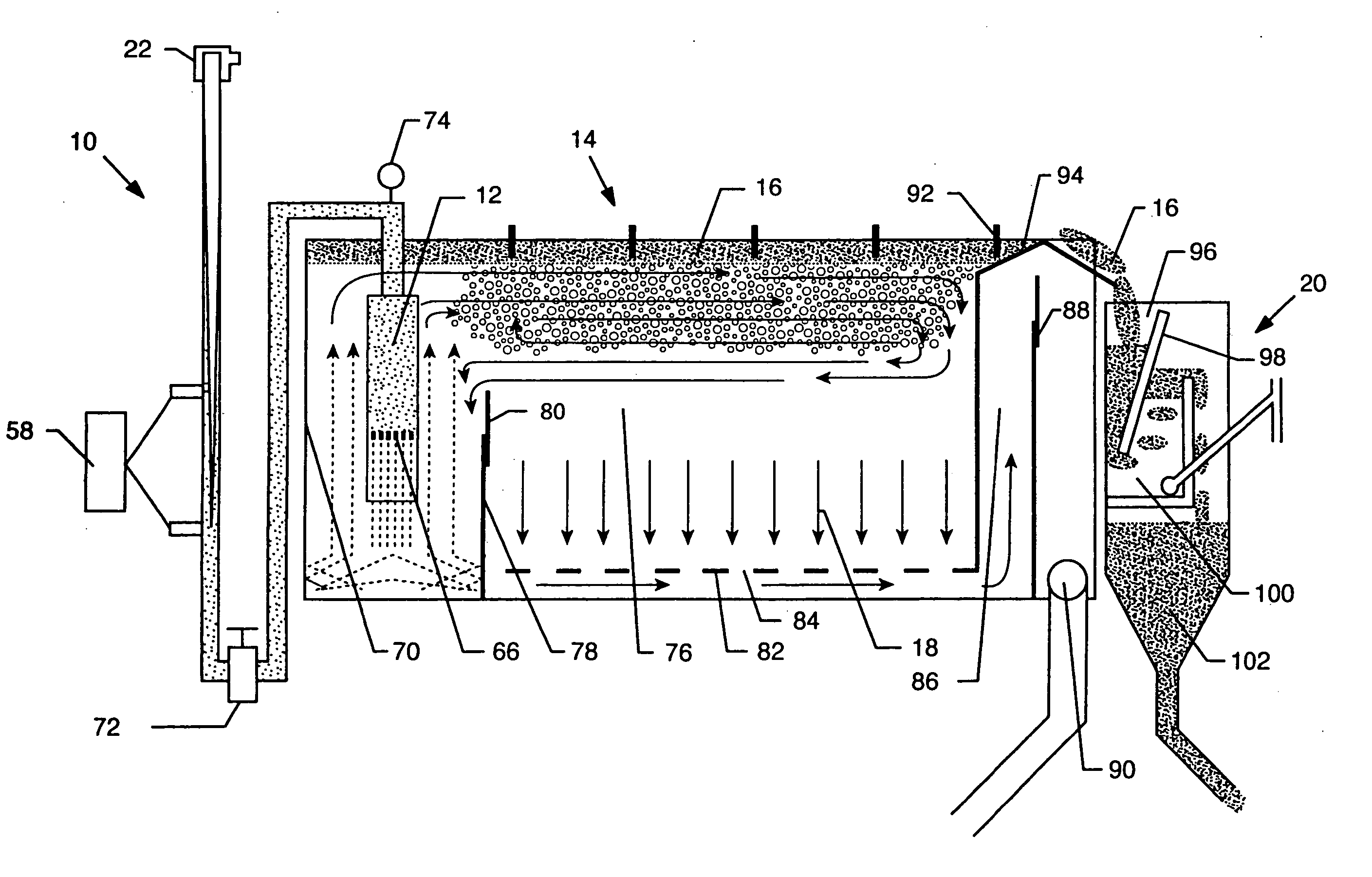
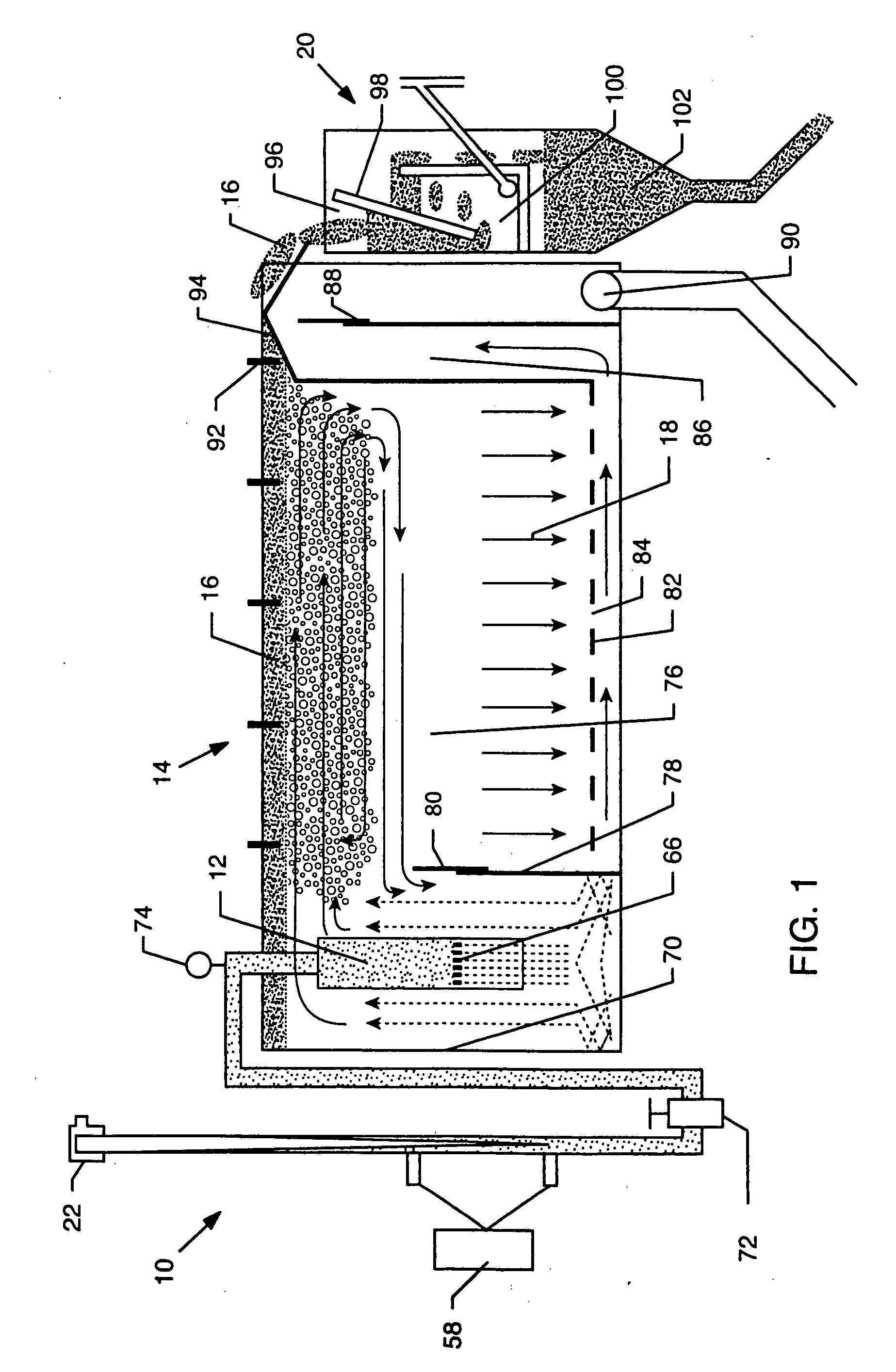
[0053] As shown in the accompanying drawings for purposes of illustration, the present invention resides in an efficient and cost-effective system for treating liquids. The system is shown in FIG. 1 and includes a mixing apparatus 10 fluidly coupled to a depressurizing device 12 which is disposed within a flotation tank 14. The mixing apparatus 10, as will be more fully described herein, is particularly designed to mix chemical additives, gas, and the like to the contaminated liquid such that the gas is entrained in the liquid at a very small size so as to adhere onto solid particles and flocculants such that as the liquid passes through the depressurizing device 12, the bubbles enlarge in size, raising the floccs and solid contaminants towards the surface of the flotation tank 14. Eventually, the floated particles form a sludge or froth 16, while the decontaminated liquid 18 sinks towards the bottom of the flotation tank 14. The froth 16 is removed to a dewatering subsystem or appa...


PUM

PropertyMeasurementUnit
diameteraaaaaaaaaa
diameteraaaaaaaaaa
diameteraaaaaaaaaa

Abstract

A system for separating particles from a contaminated liquid stream includes an apparatus for mixing the liquid with one or more separation enhancement additives and gases. A pressure reducing device having a flow restrictor element within an enlarged tube receives the mixed liquid and creates bubble laden floccs by reducing the pressure of the liquid stream. The pressure reducing device empties into a bloom chamber of a flotation tank, where the bubble laden floccs are directed upwardly to an upper portion of the flotation tank. The flotation tank is configured such that the bubble laden floccs circulate within the upper portion of the flotation tank until they float to the upper surface, while decontaminated liquid flows to a lower portion of the tank for removal. A skimmer removes the floated contaminated floccs from the upper surface of the flotation tank into a dewatering apparatus.

Description

RELATED APPLICATION [0001] This application claims priority to U.S. Provisional Patent Application Ser. No. 60 / 458,548, filed on Mar. 27, 2003; and is a continuation-in-part application of U.S. patent application Ser. No. 10 / 270,995, filed Oct. 14, 2002; and a continuation-in-part application of U.S. patent application Ser. No. 10 / 180,216, filed Jun. 25, 2002.BACKGROUND OF THE INVENTION [0002] The present invention generally relates to liquid separation components, systems and methods. More particularly, the present invention relates to a liquid flotation separation system, which occupies a much smaller footprint and can be adjusted to accommodate the changing liquid stream. [0003] It is often necessary to remove contaminants from liquid. For example, the need to remove particles, colloids, solvent and oil from wastewater is desirable in many settings. [0004] Most wastewater solid and emulsified components such as soil particles, fats, oils and grease are charged. Wastewater process...

Claims


Application Information

Patent Timeline
Patent Type & Authority Applications(United States)
IPC IPC(8): B03D1/08B03D1/14C02F1/24C02F1/38C02F9/00C02F9/02
CPCB01D19/0005B03D1/1412B01F3/0446B01F3/1207B01F5/0057B01F2215/0052B01F2215/0404B03D1/08B03D1/1431C02F1/24C02F1/38C02F1/463C02F1/56C02F1/66C02F1/682C02F1/70C02F9/00C02F2301/024C02F2301/026B03D1/1462B03D1/1493B03D1/247B03D1/028B01F1/00B01F21/00B01F23/232B01F23/51B01F25/10B01F2101/305
Inventor MORSE, DWAIN E.MORSE, WADE O.MATHERLY, THOMAS G.
Owner CLEAN WATER TECH
Why Eureka
Try Eureka