

Synchronous reluctance motor
a synchronous and reluctance technology, applied in the direction of dynamo-electric machines, magnetic circuit rotating parts, magnetic circuit shapes/forms/construction, etc., can solve the problems of increased manufacturing cost of the rotor, insufficient positive use of the reluctance torque, and increased torque ripple, so as to reduce the ripple and reduce the manufacturing cost. , the effect of large total torqu
- Summary
- Abstract
- Description
- Claims
- Application Information
AI Technical Summary
Benefits of technology
Problems solved by technology
Method used
Image

Examples
first embodiment
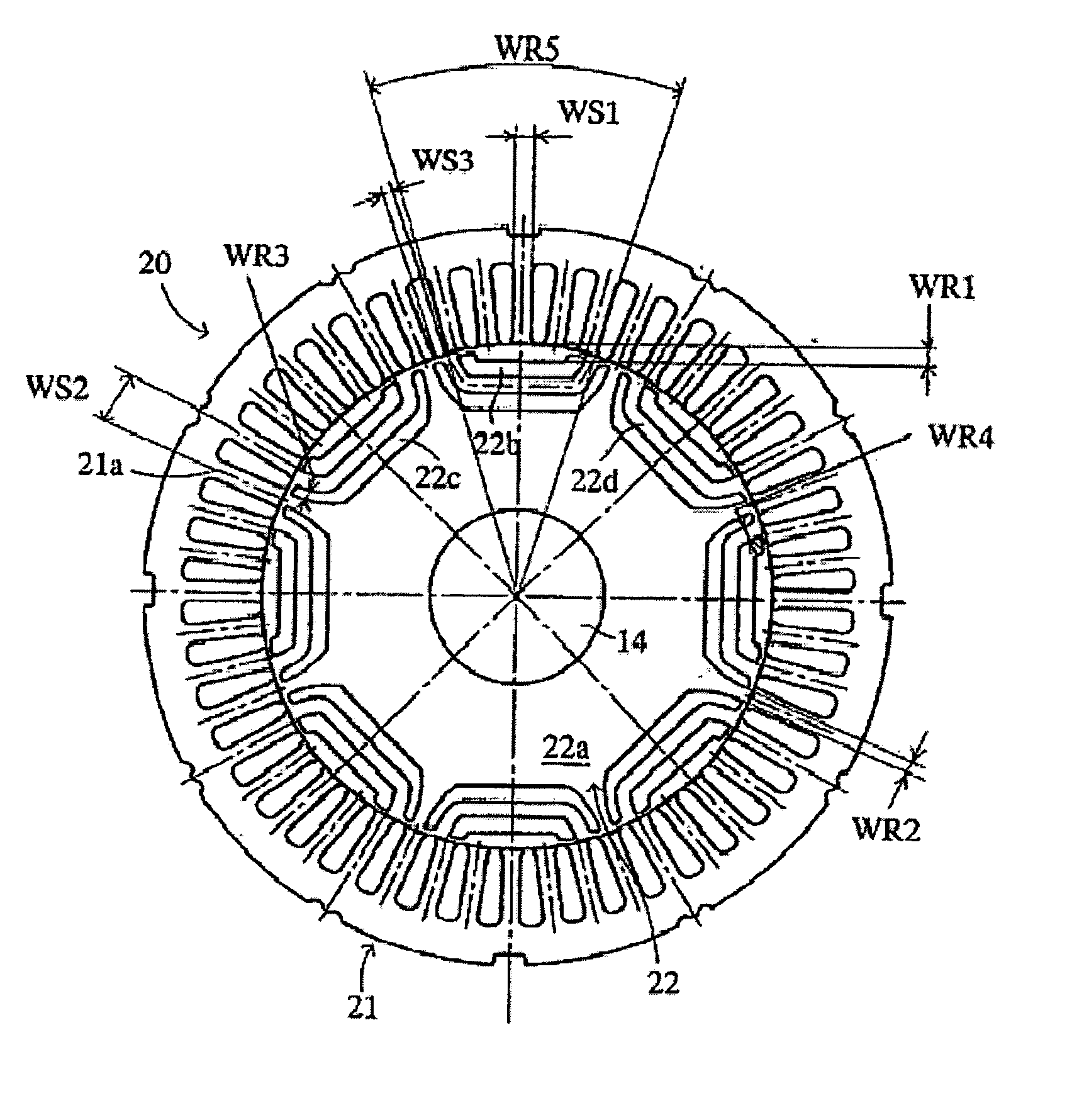
[0069] The synchronous reluctance motors 10D shown in FIG. 4, the synchronous reluctance motor according to the first aspect of the present invention was implemented, were evaluated how the relations between the maximum widths WR1 and the stator magnetic pole widths WS1 affect average torques, torque ripple ratios.
[0070] In the first embodiment, the synchronous reluctance motors 10D that the ratio of the maximum width WR1 (width defined between the outer periphery of the rotor 11 and the outer side slots 12b) relative to the stator magnetic pole widths WS1 (maximum widths WR1 / stator magnetic pole widths WS1) are determined to be each of 0.55, 0.72, 0.9, 1.07, 1.24 and 1.41 are prepared. The above synchronous reluctance motors 10D were measured or evaluated as to their static torques, and then the static torque diagrams shown in FIG. 6 were obtained. By using the static torque waveforms in FIG. 6, the average torques and the torque ripple ratios were calculated.
[0071] Each of the a...
second embodiment
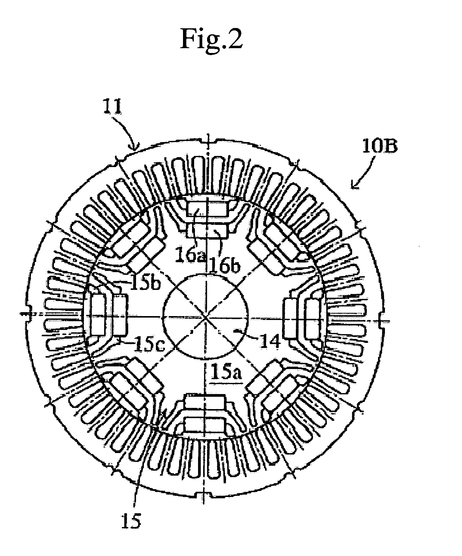
[0074] The several synchronous reluctance motors 10B, the another type of the synchronous reluctance motors having the permanent magnets that the seventh aspect of the present invention were implemented, were evaluated as to how the relationship between the maximum width WR1 and the stator magnetic pole widths WS1 affects the average torques, torque ripple ratios.
[0075] In the second embodiment, the synchronous reluctance motors 10B shown in FIG. 2 have cuboid-shaped permanent magnets embedded in the outer side slots 15b and the inner side slots 15c in the rotor. The synchronous reluctance motors 10B are further constructed to have the ratios (maximum widths WR1 / stator magnetic pole widths WS1) determined to be 0.55 or 0.90. The two synchronous reluctance motors 10B were measured or evaluated their static torque, then the static torque diagrams in FIG. 7 were obtained. As seen in the torque diagrams in FIG. 7, the static torque of the synchronous motor having the ratio 0.55 was cha...
third embodiment
[0077] The several synchronous reluctance motors 10D shown in FIG. 4 according to the first aspect of the present invention were evaluated as to how a relationship between the opening angles WR5 and the pitch angles WS2 affects the average torque and torque ripple ratio. The opening angles WR5 are formed by the lines connecting the two cross points formed by the center-line of magnetic path in the rotor core 12a and the outer periphery of the rotor 12 with the rotational center of the rotor 12. The pitch angles WS2 are formed by the center-lines of adjacent magnetic pole portion of the stator 11.
[0078] In the third embodiment, the synchronous reluctance motors 10D in which each of the ratios of the opening angles WR5 relative to the pitch angles WS2 was defined as any one of 4, 4.25, 4.4, 4.5 and 5.0 were prepared. The above synchronous reluctance motors 10D were measured or evaluated about their static torques, then the static torque diagrams shown in FIG. 8 were obtained. Even in...
PUM
 Abstract
Description
Claims
Application Information