Vehicle lamp and method of use

a technology for vehicles and lamps, applied in the field of lamps, can solve the problems of increasing power consumption and heat radiation, affecting the design flexibility of lamps, and affecting the use of lamps, so as to reduce the amount of light, brighten lamps, and reduce the effect of ligh

Inactive Publication Date: 2005-05-26
STANLEY ELECTRIC CO LTD
View PDF3 Cites 160 Cited by
  • Summary
  • Abstract
  • Description
  • Claims
  • Application Information

AI Technical Summary

Benefits of technology

[0010] In accordance with another aspect of the invention, the light emitted from the LED lamp can be reflected twice at the reflecting surfaces to redirect it toward the irradiation direction in the optical guide path extending from the LED lamp to the lens. The optical guide path can be composed of a high-refractivity material. The light emitted from the LED lamp can include differently oriented beams, which are totally reflected at the interface between the high-refractivity material and atmosphere and confined in the high-refractivity material. This operation is extremely effective to reduce the amount of light that is lost and in possibly achieving a brighter lamp.
[0011] Adjustment of the number of the second reflecting surfaces relative to the first reflecting surfaces or an increase / decrease in the number of the first reflecting surfaces can freely vary, and can vary in accordance with the number of light-emitting units per LED lamp. This can be extremely effective to provide higher design flexibility and improve the beauty of the lamp and in particular a vehicle lamp.

Problems solved by technology

A lamp having a wide area of light emission is problematic, however, because it requires many LED lamps, which elevates costs and increases power consumption and heat radiation.
Thus, it can not completely achieve a parallel light flux which results in a considerable amount of light beams radiated in directions other than expected.
These misdirected light beams can not be utilized as irradiation light from the lamp, resulting in a problem due to a lowered amount of light from the lamp.
Accordingly, variations in accuracy during assembly or in component precision may cause variations in performance among products and can possibly complicate tests in quality control.

Method used


Image

  • Vehicle lamp and method of use
  • Vehicle lamp and method of use
  • Vehicle lamp and method of use

Examples


Embodiment Construction

[0021] The present invention will now be described with reference to the exemplary embodiments shown in the drawings. Referring to the drawing figures, like reference numerals designate identical or corresponding elements throughout the several figures.

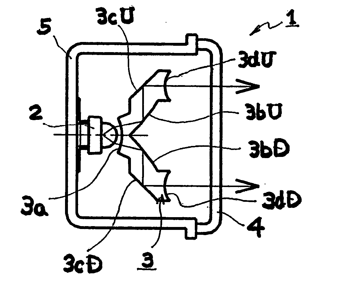
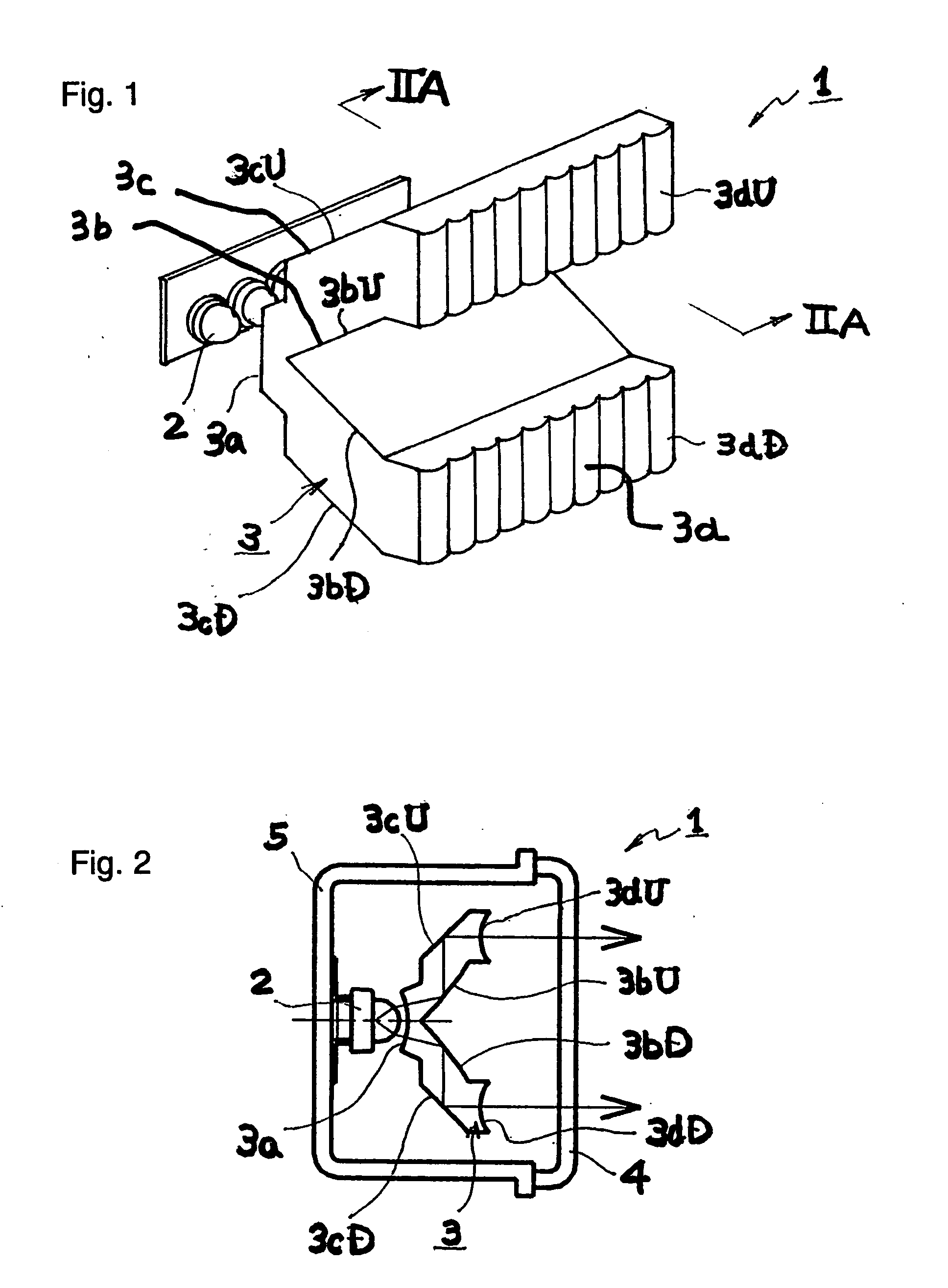
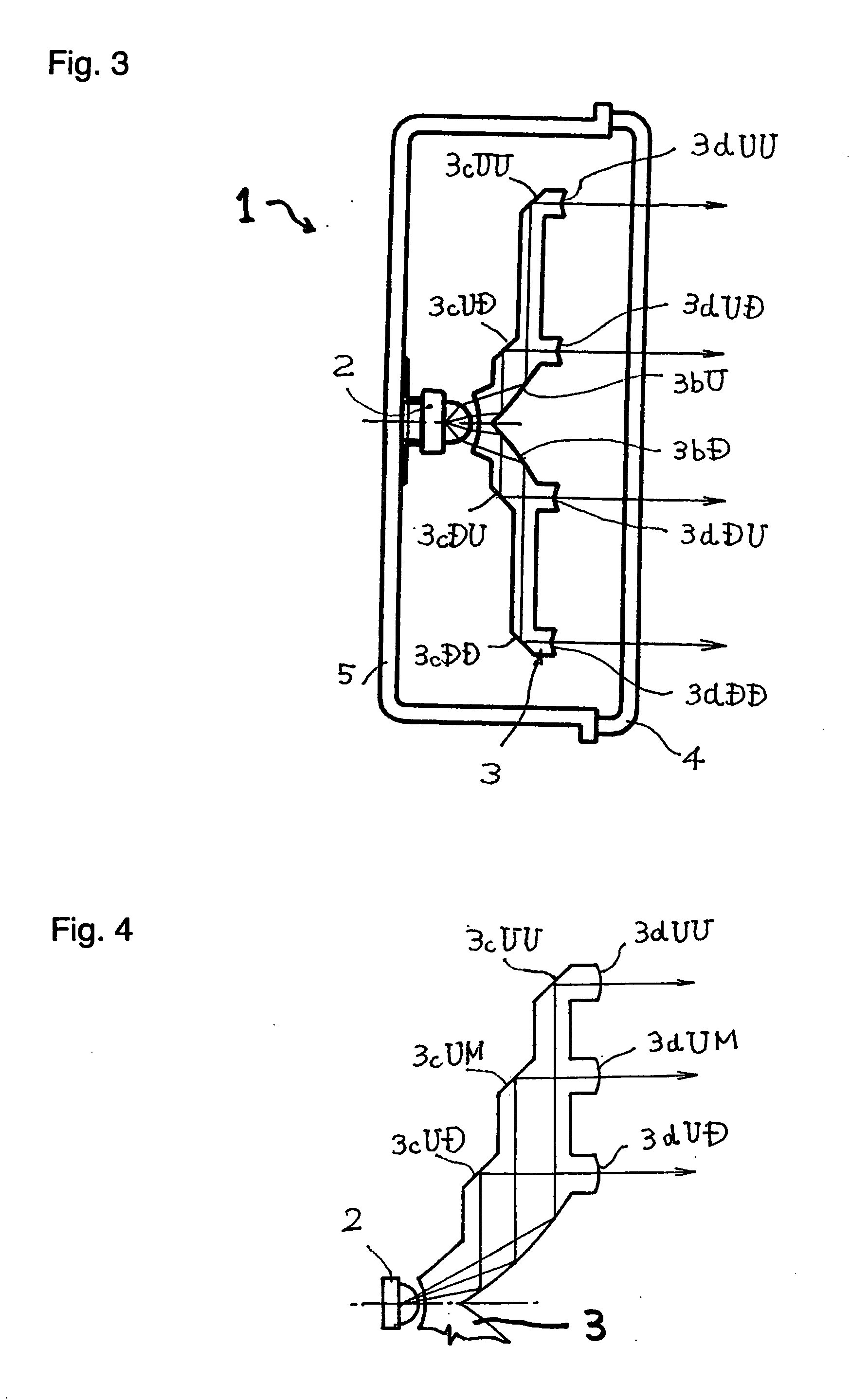
[0022]FIGS. 1 and 2 show a first embodiment of a lamp 1 made in accordance with the principles of the present invention. The lamp 1 employs LED lamps 2 as a light source. The lamp 1 as described with respect to FIG. 1 has a horizontally wide shape. However, if a vertically tall shape is required or desired, appropriate structures of the lamp as described below can be rotated 90°.

[0023] An arbitrary number of LED lamps 2 can be aligned horizontally at an appropriate interval, for example, on a printed circuit board. This enables the lamp1 to have a desired horizontal width. An optical guide path 3 can be located in front of the LED lamps 2. The optical guide path 3 is preferably integrally formed of a transparent resin material with ...


PUM


Abstract

A lamp can include LED lamps as a light source. An optical guide path including a first reflecting surface and a second reflecting surface can be provided between the LED lamp and a lens that radiates an illumination light. The optical guide path can be integrally composed of a high-refractivity material. Thus, the light passing through the optical guide path can more efficiently reach the lens. In addition, the integral optical guide path requires less assembly and thus can improve accuracy of assembly and can possibly result in a large gain in the amount of light emitted from the lamp.

Description

[0001] This application claims the priority benefit under 35 U.S.C. §119 of Japanese Patent Application No. 2003-3929354, filed on Nov. 21, 2003, which is hereby incorporated by reference.BACKGROUND OF THE INVENTION [0002] 1. Filed of the Invention [0003] The present invention relates to a lamp, and more particularly to a configuration of a vehicle lamp that employs LED lamps as a light source, along with its method of use. [0004] 2. Description of the Related Art [0005] A vehicle lamp may be configured to employ LED lamps as a light source. In such a case, initially, the LED lamps can be aligned in a matrix of rows and columns, for example, on a surface of a printed circuit board. The LED lamps can be covered from above using a cover lens, such as a fish-eye lens, which has an appropriate lens cut. A lamp having a wide area of light emission is problematic, however, because it requires many LED lamps, which elevates costs and increases power consumption and heat radiation. [0006] T...

Claims


Application Information

Patent Timeline
Patent Type & Authority Applications(United States)
IPC IPC(8): B60Q1/26F21S8/10F21V5/00F21V7/00F21V7/04F21V13/04F21Y101/02
CPCB60Q1/2696F21S48/215F21S48/2212F21S48/2225Y10S362/80F21V7/0091F21Y2101/02F21Y2113/00F21S48/236F21Y2115/10F21S43/14F21S43/26F21S43/235F21S43/315
Inventor SUZUKI, NOBUYUKICHIKAMA, HIROYUKIOKADA, HIDETAKA
Owner STANLEY ELECTRIC CO LTD
Why Eureka
Try Eureka