Aerodynamic window for generating and characterizing a filament

a filament and aerodynamic window technology, applied in the direction of laser details, optical resonator shape and construction, instruments, etc., can solve the problem of fundamental problems of direct measurements

Inactive Publication Date: 2005-05-26
DIELS JEAN CLAUDE
View PDF9 Cites 6 Cited by
  • Summary
  • Abstract
  • Description
  • Claims
  • Application Information

AI Technical Summary

Problems solved by technology

In both cases, direct measurements have faced a fundam

Method used


Image

  • Aerodynamic window for generating and characterizing a filament
  • Aerodynamic window for generating and characterizing a filament
  • Aerodynamic window for generating and characterizing a filament

Examples


Embodiment Construction

[0043] In the following detailed description, reference is made to the accompanying drawings which form a part hereof, and in which is shown by way of illustration specific embodiments in which the invention may be practiced. These embodiments are described in sufficient detail to enable those skilled in the art to practice the invention, and it is to be understood that the embodiments may be combined, or that other embodiments may be utilized and that structural, logical and electrical changes may be made without departing from the spirit and scope of the present invention. The following detailed description is, therefore, not to be taken in a limiting sense.

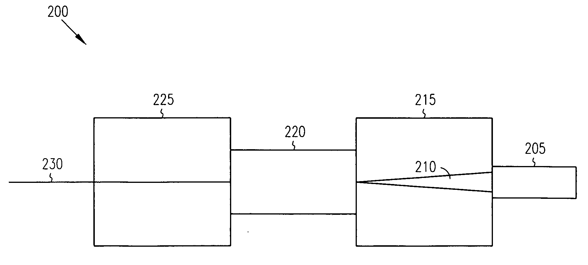
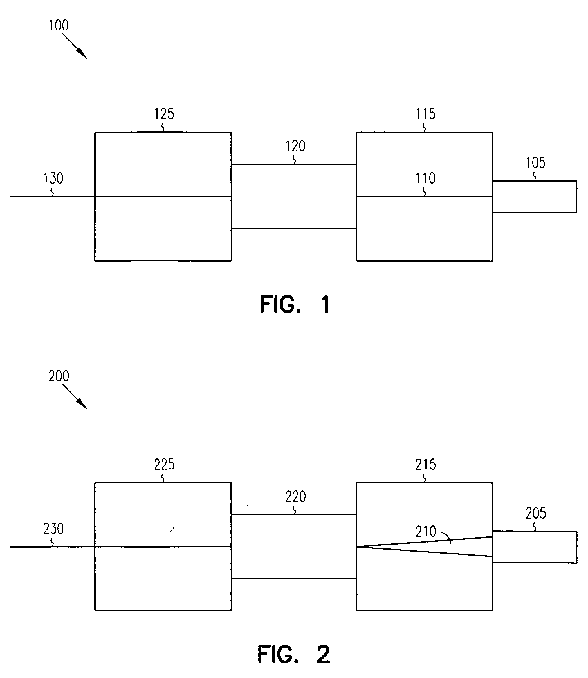
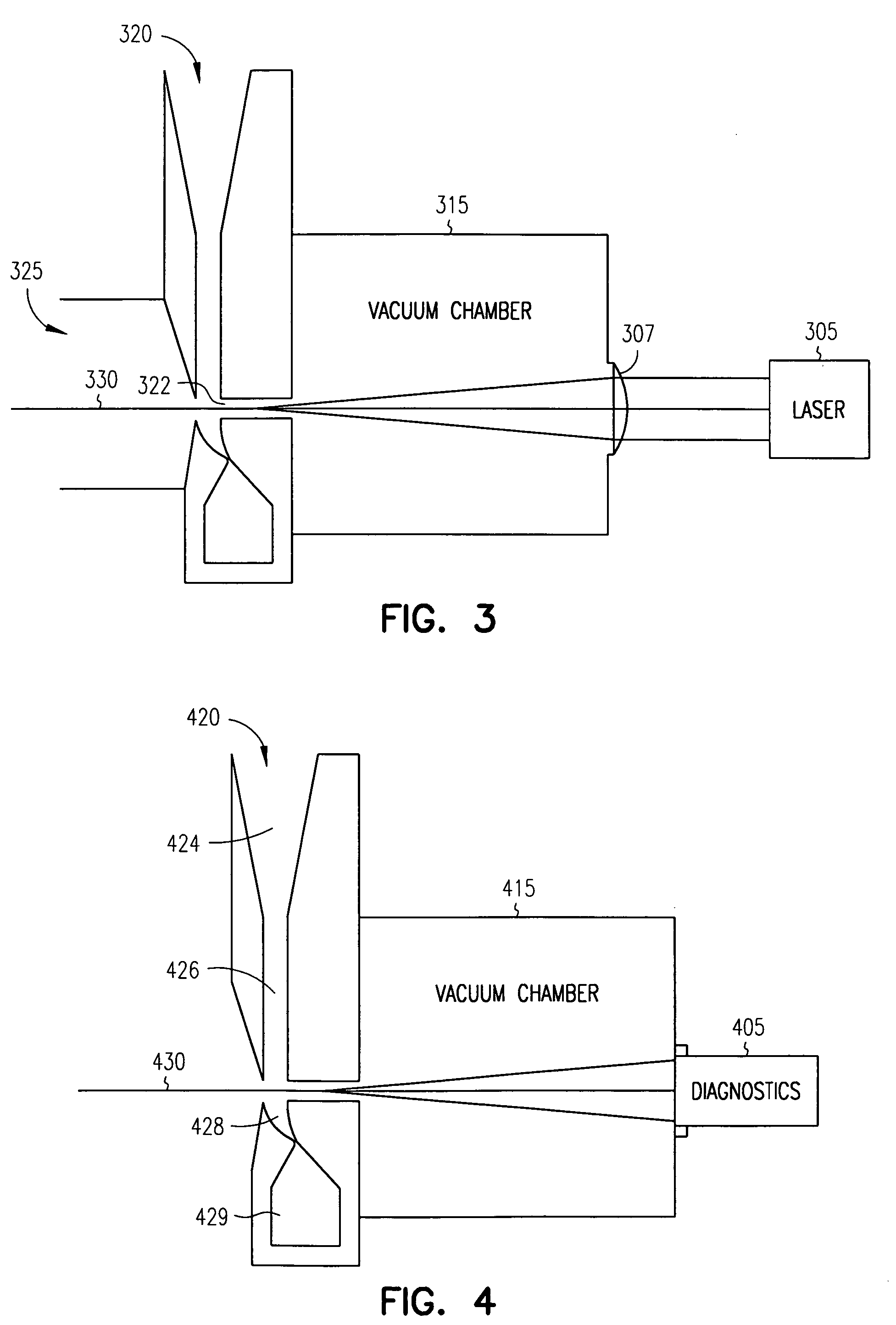
[0044] In an embodiment, a system includes a laser source and an aerodynamic window to generate a filament, a self-induced waveguide in air. The filament is the result of a balance between the collapse of a beam of high power laser pulses traversing an atmosphere and a higher order effect within the traversed atmosphere. An ae...


PUM


Abstract

A system and method for launching and characterizing filaments are provided using an aerodynamic window. A filament, a self-induced waveguide in air, is produced by high power laser pulses traversing the atmosphere that can self-focus due to the nonlinear index of refraction of air. At some critical power, self-focusing overcomes diffraction in the atmosphere and the beam collapses until it is balanced by some higher order effect, usually plasma de-focusing. The use of an aerodynamic window provides an opening for a laser beam to propagate between two different atmospheric regions without the use of a solid window, such as between the atmosphere and a vacuum. An aerodynamic window provides a means for controllably launching a filament into the atmosphere. Additionally, an aerodynamic window allows for the characterizing evaluation of a filament without damage to the optical diagnostic tools.

Description

RELATED APPLICATION [0001] This application claims priority under 35 U.S.C. 119(e) from U.S. Provisional Application Ser. No. 60 / 524,242 filed Nov. 21, 2003, which application is incorporated herein by reference.FIELD OF THE INVENTION [0002] This invention relates generally to self-induced waveguides in the atmosphere. BACKGROUND OF THE INVENTION [0003] High power laser pulses traversing the atmosphere can self-focus due to the nonlinear index of refraction of air. At some critical power, self-focusing overcomes diffraction and the beam collapses until it is balanced by some higher order effect, usually, but not exclusively, attributed to plasma de-focusing. This balance can lead to the formation of a filament, a self-induced waveguide in air. Filaments have been seen in the infrared (IR) as well as in the ultraviolet (UV) regime. In both cases, direct measurements have faced a fundamental problem, namely that the high intensity (approx. 1 TW / cm2 in the UV and up to 100 TW / cm2 in th...

Claims


Application Information

Patent Timeline
IPC IPC(8): G02F1/35H01S3/11
CPCG02F1/3511
Inventor DIELS, JEAN-CLAUDE
Owner DIELS JEAN CLAUDE
Why Eureka
Try Eureka