Laser assisted riser disconnect and method of use

a technology of laser and riser, which is applied in the direction of sealing/packing, mechanical equipment, and wellbore/well accessories, etc., can solve the problems of inability to seal off the tubular, the bop is subject to substantial force and extreme conditions, and the drilling equipment, such as the riser, is subject to the extreme conditions,

Active Publication Date: 2012-08-30
FORO ENERGY
View PDF29 Cites 58 Cited by
  • Summary
  • Abstract
  • Description
  • Claims
  • Application Information

AI Technical Summary

Benefits of technology

[0041]Still further, there is provided a method of performing drilling, workover, intervention, completion or service activities on a subsea well by using a laser module associated with a riser section, the method including: positioning a riser between the surface of a body of water and a seafloor, the riser including a riser cavity defined by the riser, wherein the riser is in fluid communication with a subsea well and an offshore rig, vessel or platform; associating a laser module with the riser, wherein the laser module comprises a laser cutter for emitting a laser beam that defines a beam path and wherein the beam path is directed from the laser cutter toward a component of the riser; and, performing activities on the well by advancing structures through the riser cavity; thereby providing the capability to fire a laser beam from the laser module to completely cut the riser in the beam path, thereby weakening the riser and providing a controlled disconnection of the riser.

Problems solved by technology

When drilling at these deep, very-deep and ultra-deep depths the drilling equipment is subject to the extreme conditions found in the depths of the ocean, including great pressures and low temperatures at the seafloor.
As such, the drilling equipment, such as drill pipe, casing, risers, and the BOP are subject to substantial forces and extreme conditions.
Pipe ram preventers and annular preventers typically can only seal the annulus between a tubular in the BOP and the BOP cavity; they cannot seal-off the tubular.
Additionally, in emergency situations, the pipe ram and annular preventers may not be able to form a strong enough seal around the tubular to prevent flow through the annulus between the tubular and the BOP cavity.
In an attempt to meet these ongoing and increasingly important needs, BOPs have become larger, heavier and more complicated.
The ever-increasing size and weight of BOPs presents significant problems, however, for older drilling rigs.
Many of the existing offshore rigs do not have the deck space, lifting capacity, or for other reasons, the ability to handle and use these larger more complicated BOP stacks.
In others situations, such as weather related situations, there may be insufficient time to pull the riser string once sufficient weather information is obtained; thus forcing a decision to potentially unnecessarily pull the riser.
Mark Zediker and those working with him at Foro Energy, Inc., Littleton Colo., it was believed that the transmission of high power laser energy over great distances without substantial loss of power was unobtainable.
It is to be noted that this incorporation by reference herein does not provide any right to practice or use the inventions of these applications or any patents that may issue therefrom and does not grant, or give rise to, any licenses thereunder.

Method used


Image

  • Laser assisted riser disconnect and method of use
  • Laser assisted riser disconnect and method of use
  • Laser assisted riser disconnect and method of use

Examples


Embodiment Construction

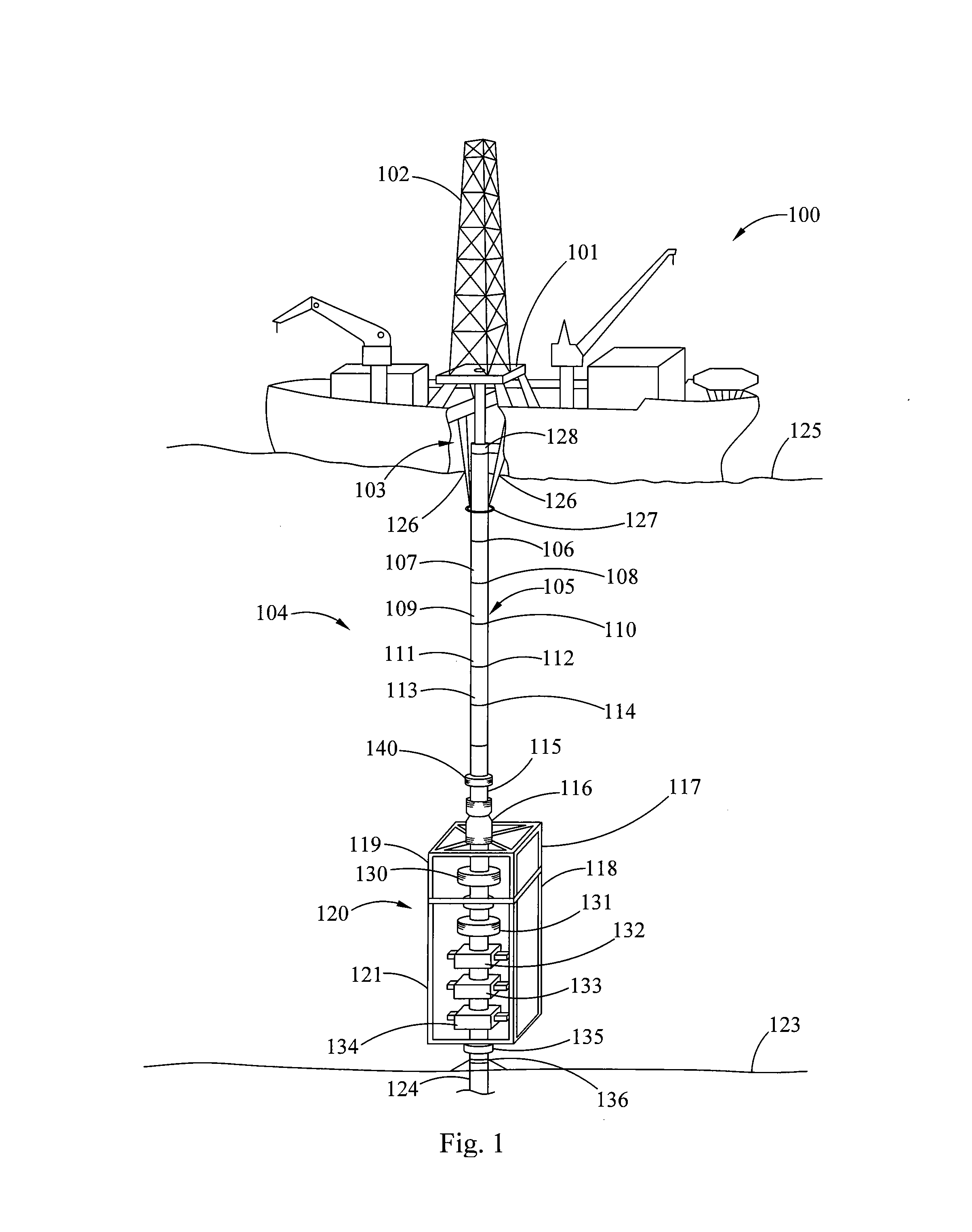
[0058]In general, the present inventions relate to laser assemblies such as laser modules for risers having high power laser beam cutters, laser riser sections, and laser-riser BOP packages utilizing such modules and sections. Thus, by way of example, an embodiment of a laser-riser BOP package having laser modules is schematically shown in FIG. 1. In this embodiment there is provided a dynamically positioned (DP) drill ship 100 having a drill floor 101, a derrick 102 above the drill floor, and moon pool 103 (as seen by the cutaway in the figure showing the interior of the drill ship 100) below the drill floor 101 and other drilling and drilling support equipment and devices utilized for operation, which are known to the offshore drilling arts, but are not shown in the figure. The drill ship includes a laser-riser BOP package 104. Although a drill ship is shown in this embodiment, any other type of offshore drilling rig, vessel or platform including FPSOs, or GGSOs, may be utilized a...


PUM


Abstract

There is provided a high power laser-riser blowout preventer package and laser module for use with a subsea riser. The laser module and laser-riser package use high power laser energy to quickly cut the riser permitting an offshore drilling rig to quickly, and in a controlled manner disconnect from a blowout preventer.

Description

BACKGROUND OF THE INVENTION[0001]1. Field of the Invention[0002]The present inventions relate to risers that are used for offshore exploration and production of hydrocarbons, such as oil and natural gas. Thus, and in particular, the present inventions relate to novel laser modules for use with risers to quickly disconnect the riser from either an offshore drilling rig, a subsea blowout preventer or both.[0003]As used herein, unless specified otherwise the terms “blowout preventer,”“BOP,” and “BOP stack” are to be given their broadest possible meaning, and include: (i) devices positioned at or near the borehole surface, e.g., the seafloor, which are used to contain or manage pressures or flows associated with a borehole; (ii) devices for containing or managing pressures or flows in a borehole that are associated with a subsea riser; (iii) devices having any number and combination of gates, valves or elastomeric packers for controlling or managing borehole pressures or flows; (iv) a s...

Claims


Application Information

Patent Timeline
Patent Type & Authority Applications(United States)
IPC IPC(8): E21B29/12E21B7/12
CPCE21B7/12E21B19/004F16L23/003E21B33/038E21B33/06E21B29/12E21B33/064
Inventor ZEDIKER, MARK S.BERGERON, HENRY A.CLARK, PHILIP V.FAIRCLOTH, BRIAN O.MOXLEY, JOEL F.DEUTCH, PAUL D.RINZLER, CHARLES C.
Owner FORO ENERGY
Why Eureka
Try Eureka