Laser assisted system for controlling deep water drilling emergency situations

a technology of assisted system and deep water drilling, which is applied in the direction of drilling pipe, sealing/packing, and well accessories, etc., can solve the problems of inability to seal off the tubular, the drilling equipment is and the drilling equipment, such as the drill pipe, the riser, and the bop, are subject to the extreme conditions and extreme forces

Active Publication Date: 2012-08-30
FORO ENERGY
View PDF17 Cites 70 Cited by
  • Summary
  • Abstract
  • Description
  • Claims
  • Application Information

AI Technical Summary

Benefits of technology

[0037]Moreover, there is provided a method of performing drilling, workover, intervention, completion or service on a subsea well by using a laser riser and blowout preventer system in conjunction with an offshore drilling rig to control and manage potential emergency and emergency situations, the method including: lowering a blowout preventer, from an offshore drilling rig, vessel or platform to a seafloor using a riser including a plurality of riser sections; wherein the blowout preventer includes: a blowout preventer cavity defined by the blowout preventer; and a first laser cutter for emitting a first laser beam that defines a first beam path, wherein the first beam path is directed toward the blowout preventer cavity; wherein the riser includes: a riser cavity defined by the riser; and a second laser cutter for emitting a second laser beam that defines a second beam path, wherein the second beam path is directed toward a component of the riser; operably connecting a high power laser into a control system; securing the blowout preventer to a borehole, whereby the borehole cavity and the riser cavity are in fluid and mechanical communication; and, performing operations on the borehole by lowering structures from the offshore drilling rig down through the riser cavity, the blowout preventer cavity and into the borehole; and, wherein, the control system is configured to fire the high power laser. Further, the structures may be selected from the group consisting of: tubulars, wireline, coiled tubing and slickline.

Problems solved by technology

When drilling at these deep, very-deep and ultra-deep depths the drilling equipment is subject to the extreme conditions found in the depths of the ocean, including great pressures and low temperatures at the seafloor.
As such, the drilling equipment, such as drill pipe, casing, risers, and the BOP are subject to substantial forces and extreme conditions.
Pipe ram preventers and annular preventers typically can only seal the annulus between a tubular in the BOP and the BOP cavity; they cannot seal-off the tubular.
Additionally, in emergency situations, the pipe ram and annular preventers may not be able to form a strong enough seal around the tubular to prevent flow through the annulus between the tubular and the BOP cavity.
In an attempt to meet these ongoing and increasingly important needs, BOPs have become larger, heavier and more complicated.
The ever-increasing size and weight of BOPs presents significant problems, however, for older drilling rigs.
Many of the existing offshore rigs do not have the deck space, lifting capacity, or for other reasons, the ability to handle and use these larger more complicated BOP stacks.
In others situations, such as weather related situations, there may be insufficient time to pull the riser string once sufficient weather information is obtained; thus forcing a decision to potentially unnecessarily pull the riser.
In offshore drilling activities critical and often times emergency situations arise.
These situations can occur quickly, unexpectedly and require prompt attention and remedial actions.
Although these offshore emergency situations may have similar downhole causes to onshore drilling emergency situations, the offshore activities are much more difficult and complicated to manage and control.
For example, it is generally more difficult to evacuate rig personnel to a location, away from the drilling rig, in an offshore environment.
Environmentally, it is also substantially more difficult to mitigate and manage the inadvertent release of hydrocarbons, such as in an oil spill, or blowout, for an offshore situation than one that occurs onshore.
Such tubulars may also interfere with, inhibit, or otherwise prevent, well control equipment from functioning properly.
These tubulars and the riser can act as a conduit bringing dangerous hydrocarbons and other materials into the very center of the rig and exposing the rig and its personnel to extreme dangers.
Such brute force methods, however, have failed to meet this long-standing and important need
Mark Zediker and those working with him at Foro Energy, Inc., Littleton Colo., it was believed that the transmission of high power laser energy over great distances without substantial loss of power was unobtainable.
It is to be noted that this incorporation by reference herein does not provide any right to practice or use the inventions of these applications or any patents that may issue therefrom and does not grant, or give rise to, any licenses thereunder.

Method used


Image

  • Laser assisted system for controlling deep water drilling emergency situations
  • Laser assisted system for controlling deep water drilling emergency situations
  • Laser assisted system for controlling deep water drilling emergency situations

Examples


Embodiment Construction

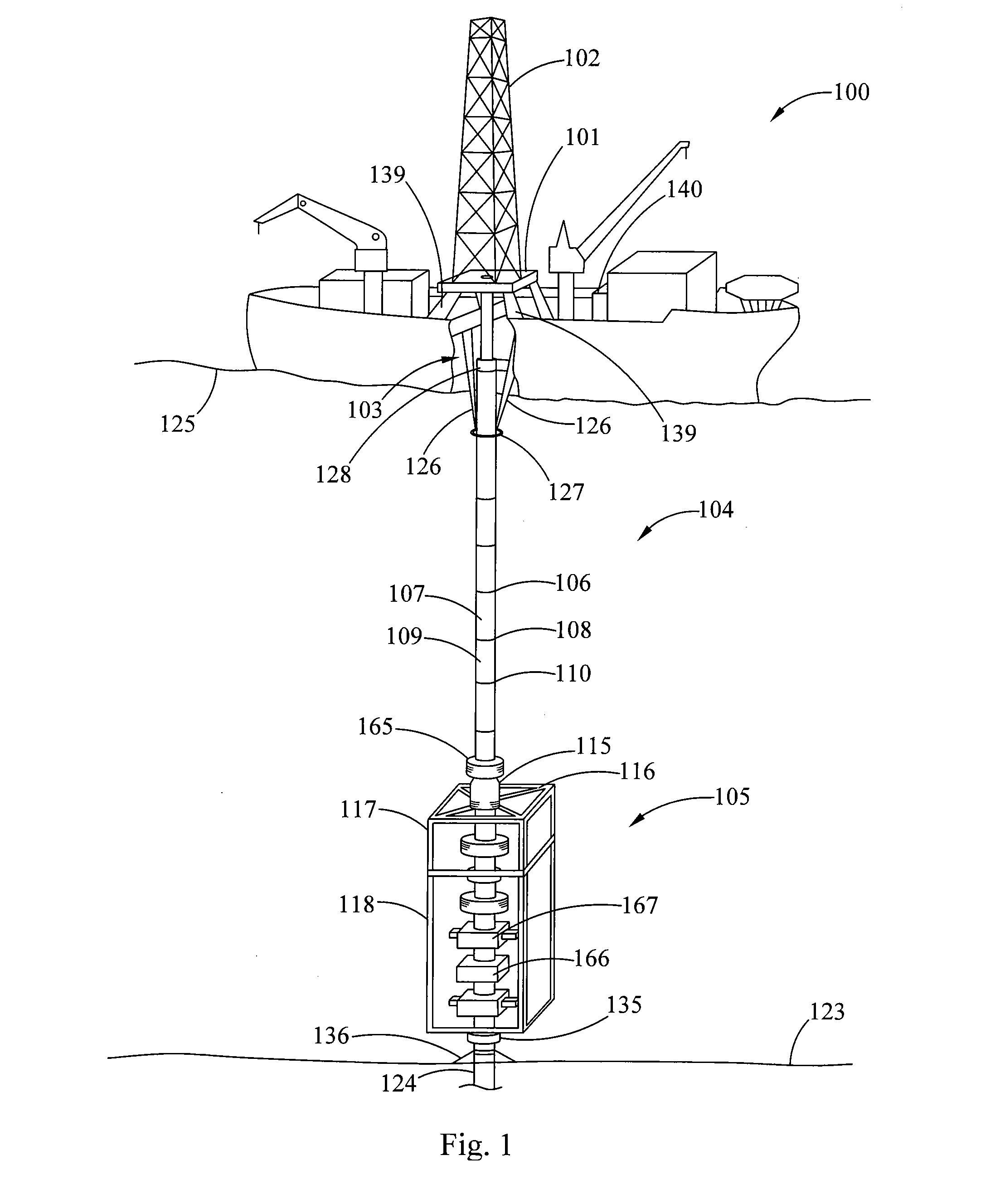
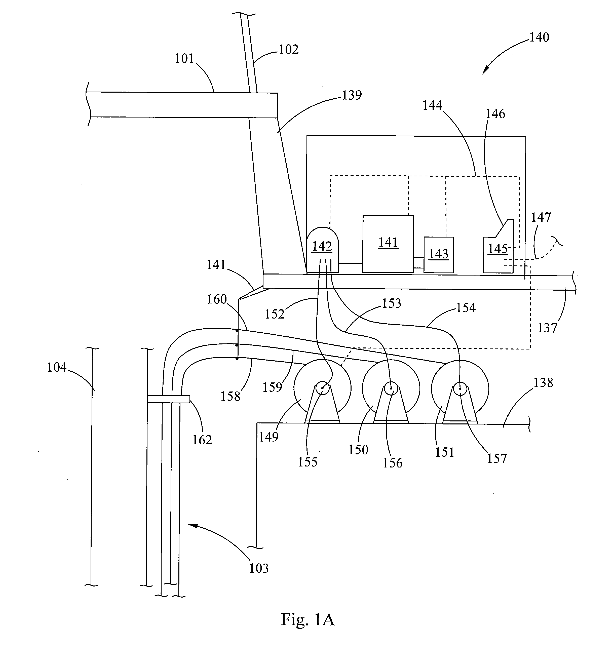
[0069]In general, the present inventions relate to multiple laser beam delivery systems that can deliver controlled, precise and predetermined laser energy to address crisis and emergency situations during offshore drilling activities. Thus, by way of example, an embodiment of an offshore drilling rig having a laser beam delivery system is schematically shown in FIG. 1. In this embodiment there is provided a dynamically positioned (DP) drill ship 100 having a drill floor 101, a derrick 102 above the drill floor, and moon pool 103 (as seen by the cutaway in the figure showing the interior of the drill ship 100) below the drill floor 101 and other drilling and drilling support equipment and devices utilized for operation, which are known to the offshore drilling arts, but are not shown in the figure. The drill ship includes a riser 104 and a BOP stack 105. Although a drill ship is shown in this embodiment, any other type of offshore drilling rig, vessel or platform, including FPSOs, o...


PUM


Abstract

There is provided a high power laser riser blowout preventer system and controller for operation thereof. The system utilizes high power laser cutters that are associated with the riser and the blowout preventer to provided an integrated operation to quickly weaken or cut tubulars to address potential emergency and emergency situations that can arise during deep sea drilling.

Description

BACKGROUND OF THE INVENTION[0001]1. Field of the Invention[0002]The present inventions relate to systems used for offshore exploration and production of hydrocarbons, such as oil and natural gas. Thus, and in particular, the present inventions relate to novel systems that utilize high power laser cutters to quickly assist in the management and control of offshore drilling emergency events.[0003]As used herein, unless specified otherwise the terms “blowout preventer,”“BOP,” and “BOP stack” are to be given their broadest possible meaning, and include: (i) devices positioned at or near the borehole surface, e.g., the seafloor, which are used to contain or manage pressures or flows associated with a borehole; (ii) devices for containing or managing pressures or flows in a borehole that are associated with a subsea riser; (iii) devices having any number and combination of gates, valves or elastomeric packers for controlling or managing borehole pressures or flows; (iv) a subsea BOP stack...

Claims


Application Information

Patent Timeline
Patent Type & Authority Applications(United States)
IPC IPC(8): E21B7/12E21B29/12
CPCE21B29/08E21B29/12E21B33/063E21B17/01E21B17/085E21B17/18
Inventor ZEDIKER, MARK S.
Owner FORO ENERGY
Why Eureka
Try Eureka