High power laser tunneling mining and construction equipment and methods of use

a technology of laser tunneling and construction equipment, applied in the direction of auxiliary welding devices, dislodging machines, ways, etc., can solve the problems of inconvenient access to ore bodies, inconvenient transportation to surface via trucks, shafts may be sunk,

Active Publication Date: 2014-08-21
FORO ENERGY
View PDF41 Cites 73 Cited by
  • Summary
  • Abstract
  • Description
  • Claims
  • Application Information

AI Technical Summary

Benefits of technology

[0071]Additionally there is provided a laser mechanical earth removing machine, having: a movable cutting assembly, the cutting assembly having a laser cutter capable of generating at least about a 10 kW laser beam having a spot size of less than about 3 cm diameter, a rotating mechanical cutting roller, the roller having a cutting wheel, the laser cutter providing a beam path cooperatively positioned with the cutting wheel.
[0072]Yet further there is provided a laser mechanical continuous mining machine, having: a rotating head having a cutting wheel; an adjustment means whereby the position of the rotating head is adjusted; an inlet chute for receiving a laser affected ore; and outlet chute for discharging a laser affected ore; a laser cutting assembly; a laser support bar, whereby the laser cutting assembly is affixed to the mining machine; and a high power laser cable in optical communication with the laser cutting assembly.
[0073]Additionally there is provided a laser mining system, the system comprising a high power laser truck, a laser robot, the laser robot having a means for directing a laser beam in a substantially vertical direction.
[0074]Still further there is further provided high power laser systems and methods having 1 kW, 10 kW, 20 kW, 40 kW or more laser energy and one or more of the following features, including: wherein the system is characterized as a Class I product; wherein the system is characterized as a Class II product; wherein the system is characterized as a Class IIa product; wherein the system is characterized as a Class IIIa product; and wherein the system is characterized as a Class IIIb product.

Problems solved by technology

Shafts may be sunk for ore bodies where haulage to surface via truck is not economical, or where access to the ore bodies is not practical.
An example of a combination of these techniques may be seen when a decline is placed into the side of the pit wall of an surface mine when, for example, the ore is of a payable grade sufficient to support an underground mining operation but the strip ratio (mineral to waste) has become too great to support surface mining operations.
At these depths the need for, and difficulties in providing electric power and the cables needed to provide such power can be considerable.
These machines can be massive, having diameter of 15 feet, 20 feet, 25 feet or more, and complex having the ability to advance the tunnel face forward while simultaneously placing supports within the tunnel.
This equipment and activities can also cause substantial vibrations and potential damage to surrounding structures.
Many times, especially in urban areas, because of the associated noise and vibrations from the use of this equipment the activities have to take place during daylight or business hours when traffic is most heavy.
The equipment and methods for mining, tunneling, earth moving and repairing infrastructure, have generally involved, dangerous, noisy, high vibration and imprecise equipment and activities, requiring for example the use of explosives or large powerful mechanical cutting and digging machines.

Method used


Image

  • High power laser tunneling mining and construction equipment and methods of use
  • High power laser tunneling mining and construction equipment and methods of use
  • High power laser tunneling mining and construction equipment and methods of use

Examples


example 1

[0214]The laser mechanical tunneling machine of the embodiment of FIG. 1 has 8 laser cutting tools of the general type shown in FIG. 11A, each tool has an adjustable optics package of the type shown in FIGS. 16A-16D, and the focal length of each tool is adjusted to 1,000 mm. Each laser tool is connected to a fiber laser system capable of providing a 40 kW laser beam. The fiber laser system provides a multimode continuous laser beam having a wavelength of about 1070 nm. Each laser tool is connected to the fiber laser system by way of an optical fiber having a core of about 300 μm, a conventional water cooled connector is used to launch the laser beam into the focusing optical elements of the optics package of the laser tool. The connector at the end of the fiber has an NA of 0.22 at the laser beam launch face (distal end) of the connector. Each laser beam when fired provides a spot size having diameter and a power density of at the proximal surface of the proximal focusing lens in th...

example 2

[0215]An embodiment of an optics assembly for providing a high power laser beam for cutting and drilling a target material from a stand off distance of 100 feet is provided in FIGS. 17A to 17C, this optics assembly is located in the laser cutting tool of the embodiment of FIG. 26. Turning to FIG. 17A there is shown a perspective schematic view of an optics assembly having two mirrors 701, 702, which their reflective surfaces facing each other. A high power laser cable 703 having a single optical fiber having a core of about 200 μm extends through the center of mirror 702 to a beam launch assembly 704. The NA of the distal face of the beam launch assembly is 0.22. The beam launch assembly 704 launches a high power laser beam, having 20 kW of power in a pattern shown by the ray trace lines, to a secondary mirror 701. The secondary mirror 701 is located 11 cm from the launch or distal face of the beam launch assembly 704. The secondary mirror 701 has a diameter of 2″ and has its convex...

example 2a

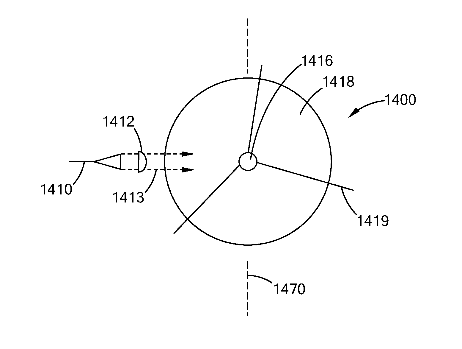
[0217]FIGS. 21A and 21B provides a side cross section schematic view and a front on view of an embodiment of a divert, convergent lens assembly along the lines of EXAMPLE 2, having a 45 degree reflector to handle and direct the incoming laser beam in collimated space, which is used with a laser cutting tool system of the type shown in FIG. 26. FIG. 21A provides a side view of this optics assembly 1400, with respect to the longitudinal axis 1470 of the tool. FIG. 21B provides a front view of optics assembly 1400 looking down the longitudinal axis 1470 of the tool. As best seen in FIG. 14A, where there is shown a side schematic view of an optics assembly having a fiber 1410 with a connector launch a beam into a collimating lens 1412. The collimating optic 1412 directs the collimated laser beam along beam path 1413 toward reflective element 1414, which is a 45° mirror assembly. Reflective mirror 1414 directs the collimated laser beam along beam path 1415 to diverging mirror 1416. Diver...


PUM

PropertyMeasurementUnit
depthaaaaaaaaaa
poweraaaaaaaaaa
poweraaaaaaaaaa

Abstract

There are provided high power laser and laser mechanical earth removing equipment, and operations using laser cutting tools having stand off distances. These equipment provide high power laser beams, greater than 1 kW to cut and volumetrically remove targeted materials and to remove laser affected material with gravity assistance, mechanical cutters, fluid jets, scrapers and wheels. There is also provided a method of using this equipment in mining, road resurfacing and other earth removing or working activities.

Description

[0001]This application: (i) claims, under 35 U.S.C. §119(e)(1), the benefit of the filing date of Dec. 24, 2012 of U.S. provisional application Ser. No. 61 / 745,661; (ii) is a continuation in part of U.S. patent application Ser. No. 14 / 080,722, filed Nov. 14, 2013 which claims under 35 U.S.C. §119(e)(1), the benefit of the filing date of Nov. 15, 2012 of U.S. provisional application Ser. No. 61 / 727,096; (iii) is a continuation in part of U.S. patent application Ser. No. 13 / 782,869, filed Mar. 1, 2013, which claims, under 35 U.S.C. §119(e)(1), the benefit of the filing date of Mar. 1, 2012 of U.S. provisional application Ser. No. 61 / 605,429; (iv) is a continuation in part of U.S. patent application Ser. No. 13 / 768,149, filed Aug. 15, 2013 which claims, under 35 U.S.C. §119(e)(1), the benefit of the filing date of Mar. 1, 2012 of U.S. provisional application Ser. No. 61 / 605,434; (v) is a continuation-in-part of U.S. patent application Ser. No. 13 / 222,931 filed Aug. 31, 2011, which clai...

Claims


Application Information

Patent Timeline
Patent Type & Authority Applications(United States)
IPC IPC(8): B23K26/00E21B7/15E01C23/12E21C41/00E21D9/10E01C23/08B23K26/38E21C37/18
CPCB23K26/0093B23K26/381E21B7/15E21C37/18E21C41/00E21D9/1073E01C23/08E01C23/12B23K26/382B23K26/402B23K37/0294B23K37/0288B23K2103/30B23K26/0622B23K26/0626B23K26/03B23K26/703B23K26/0648B23K26/14B23K26/1476B23K26/0676B23K26/0604E01C23/088E01C23/128E21C37/16E21C25/66E21D9/08B23K26/40B23K2103/50B23K2103/52E21C25/64E21C27/24
Inventor LAND, MARK S.VOLKMAR, JOHN F.ZEDIKER, MARK S.KOLACHALAM, SHARARTHNORTON, RYAN J.FAIRCLOTH, BRIAN O.GRUBB, DARYL L.DE WITT, RONALD A.
Owner FORO ENERGY
Why Eureka
Try Eureka