Downhole deep tunneling tool and method using high power laser beam

a laser beam and deep tunnel technology, applied in the direction of drilling machines and methods, wellbore/well accessories, insulation, etc., can solve the problems of hydraulic fracture fluid damage to the formation, the risk of explosive handling at the surface, and the possibility of melt formation in the tunnel

Active Publication Date: 2014-12-11
SAUDI ARABIAN OIL CO
View PDF0 Cites 71 Cited by
  • Summary
  • Abstract
  • Description
  • Claims
  • Application Information

AI Technical Summary

Benefits of technology

[0009]In one embodiment of the present invention, the downhole laser tool for penetrating a hydrocarbon bearing formation includes a laser surface unit configured to generate a high power laser beam. The laser surface unit is in electrical communication with a fiber optic cable. The fiber optic cable is configured to conduct the high power laser beam. The fiber optic cable includes an insulation cable configured to resist high temperature and high pressure, a protective laser fiber cable configured to conduct the high power laser beam, a laser surface end configured to receive the high power laser beam, a laser cable end configured to emit a raw laser beam from the fiber optic cable. The downhole laser tool includes an outer casing placed within an existing wellbore, which extends within a hydrocarbon bearing formation, a hard case placed within the outer casing, wherein the fiber optic cable is contained within the hard case, and a rotational system positioned within the outer casing. The rotational system includes a rotational casing coupled to the end of the hard case and a rotational head extending from the rotational casing. The rotational system is configured to rotate around the axis of the hard case. The rotational head includes a focusing system configured to direct the raw laser bea

Problems solved by technology

There is the potential for melt to form in the tunnel.
There is a risk in involved while handling the explosives at the surface.
The hydraulic fracture fluids can be damaging to the formation, specifically shale rocks.
First, as noted above, hydraulic fracturing can be damaging to the formation.
Additionally, there is no control over the direction of the fracture.
There are ris

Method used


Image

  • Downhole deep tunneling tool and method using high power laser beam
  • Downhole deep tunneling tool and method using high power laser beam
  • Downhole deep tunneling tool and method using high power laser beam

Examples


Embodiment Construction

[0031]While the invention will be described with several embodiments, it is understood that one of ordinary skill in the relevant art will appreciate that many examples, variations and alterations to the apparatus and methods described herein are within the scope and spirit of the invention. Accordingly, the exemplary embodiments of the invention described herein are set forth without any loss of generality, and without imposing limitations, on the claimed invention.

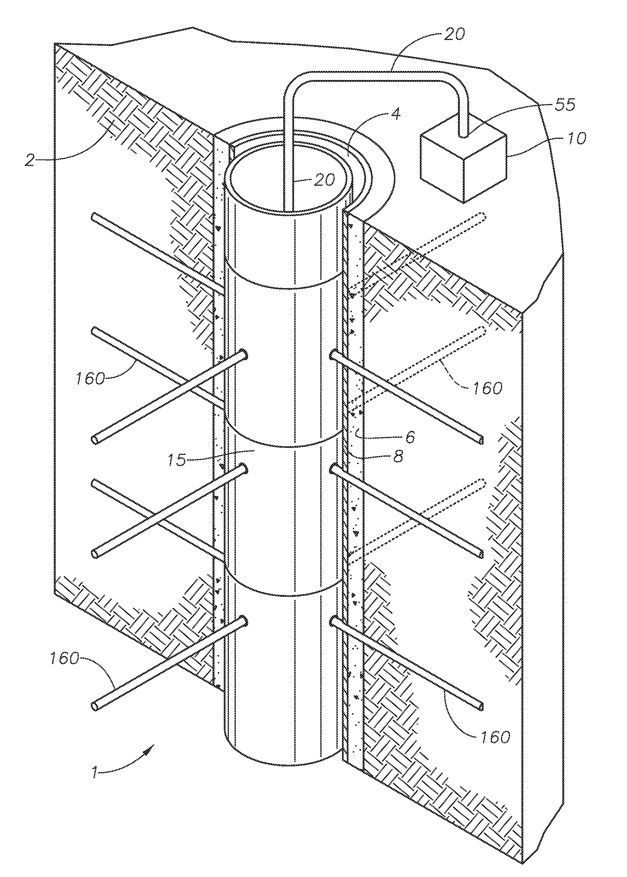
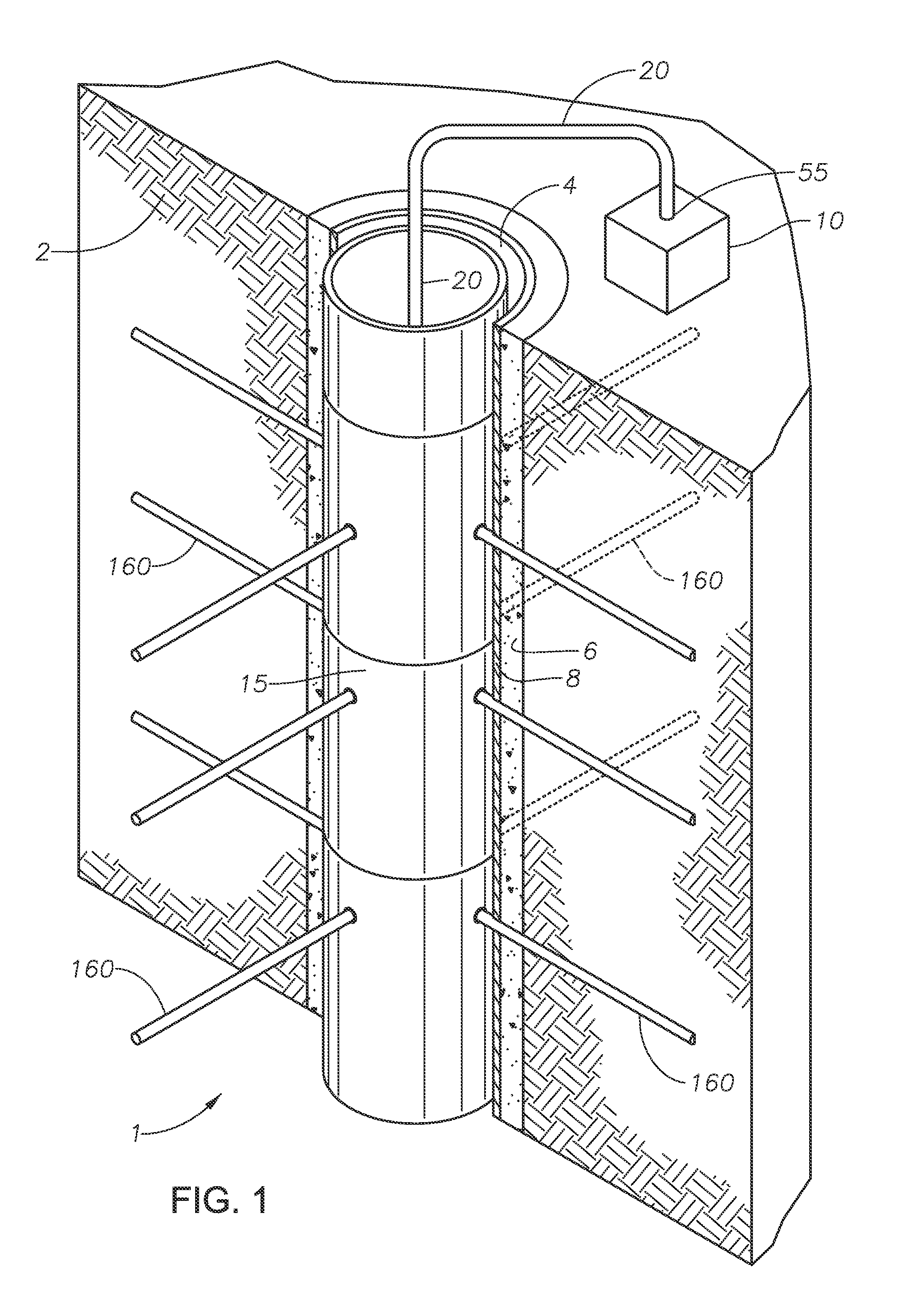
[0032]FIG. 1 depicts a perspective view of a downhole laser tool in accordance with one embodiment of this invention. Laser surface unit 10 sits on the surface of the earth near existing wellbore 4. Existing wellbore 4 has been dug into hydrocarbon bearing formation 2, with cement 6 and wellbore casing 8 as reinforcement. Downhole laser tool head (not shown) sits within existing wellbore 4. Laser surface unit 10 is in electrical communication with fiber optic cable 20. Laser surface unit 10 is connected to laser surface ...


PUM


Abstract

A downhole laser tool for penetrating a hydrocarbon bearing formation includes a laser surface unit to generate a high power laser beam, a fiber optic cable to conduct the high power laser beam from the laser surface unit to a rotational system that has a rotational head which includes a focusing system and a downhole laser tool head, the focusing system includes a beam manipulator, a focused lens, and a collimator, the downhole laser tool head includes a first cover lens to protect the focusing system, a laser muzzle to discharge the collimated laser beam from the downhole laser tool head into the hydrocarbon bearing formation, a fluid knife to sweep the first cover lens, a purging nozzle to remove dust from the path of the collimated laser beam, a vacuum nozzle to collect dust and vapor from the path of the collimated laser beam.

Description

FIELD OF THE INVENTION[0001]This invention relates to a method and apparatus for penetrating a hydrocarbon bearing formation. More specifically, this invention relates to a method and apparatus for sublimating hydrocarbon bearing formations using a downhole laser tool for the purpose of building a network.BACKGROUND OF THE INVENTION[0002]Wellbore stimulation is a branch of petroleum engineering focused on ways to enhance the flow of hydrocarbons from a formation to the wellbore for production. To produce hydrocarbons from the targeted formation, the hydrocarbons in the formation need to flow from the formation to the wellbore in order to be produced and flow to the surface. The flow from the formation to the wellbore is carried out by the means of formation permeability. When formation permeability is low, stimulation is applied to enhance the flow. Stimulation can be applied around the wellbore and into the formation to build a network in the formation.[0003]The first step for stim...

Claims


Application Information

Patent Timeline
IPC IPC(8): E21B7/15
CPCE21B7/15E21B7/046E21B7/14
Inventor BATARSEH, SAMEEH ISSA
Owner SAUDI ARABIAN OIL CO
Why Eureka
Try Eureka