Laser systems and methods for the removal of structures

a laser system and structure technology, applied in the direction of special purpose vessels, vessel construction, borehole/well accessories, etc., can solve the problems of complex and varied steps of plugging, abandoning and decommissioning, and no longer be economically producing hydrocarbons, etc., to achieve the effect of lessening the weight of the structur

Active Publication Date: 2014-08-21
FORO ENERGY
View PDF5 Cites 65 Cited by
  • Summary
  • Abstract
  • Description
  • Claims
  • Application Information

AI Technical Summary

Benefits of technology

[0029]Thus, there is provided a method of and system for removing a section of a member from an offshore structure, the method and system including: operably associating a high power laser system with the offshore structure, the high power laser system including a high power laser and a high power laser cutting tool; the high power laser cutting tool defining a laser beam delivery path for delivery of a high power laser beam along the beam path; positioning the laser cutting tool adjacent a member of the offshore structure, whereby the laser beam path extends from the cutting tool to the member; propagating a high power laser beam along the beam path and moving the beam path and laser beam thereby cutting the member, whereby a section of the member is formed in a predetermined manner; and, removing the section from the structure.

Problems solved by technology

At some point in time, a well or a collection of wells, will no longer be economically producing hydrocarbons.
As with the steps to drill for and produce hydrocarbons, the steps for plugging, abandoning and decommissioning are complex and varied.
All of these methodologies have health, safety, environmental, and reliability drawbacks.
. . does not have guaranteed success and many cuts were repeated or completed with divers working inside the caisson legs after [abrasive water jet] cuts proved to be incomplete.”
Diamond saws and mechanical cutters have similar reliability failings.
Diamond saws, as well as, abrasive water jets, are also slow in making their cuts, and thus, can be time consuming, which along with other factors, greatly adds to the overall removal costs.
Oxygen-arc or torch cutters are similarly slow, may require divers, and thus, subject the divers to hazardous conditions, such as being inside of a caisson.
Additionally, these cutters will not cut all types of material, for example concrete, which may require for example a diver to chip the cement away.
Explosives, although reliable are dangerous to both humans and marine life, and in particular, to marine mammals.
The abrasives used in abrasive water jets also have environmental concerns, although the study of this has only recently been started.
The abrasive material used may prove dangerous to marine life and harmful to the environment.
Prior to the recent breakthroughs of Foro Energy co-inventors it was believed that the transmission of high power laser energy over great distances without substantial loss of power was unobtainable.

Method used


Image

  • Laser systems and methods for the removal of structures
  • Laser systems and methods for the removal of structures
  • Laser systems and methods for the removal of structures

Examples


example 1

[0237]Biologic growth on a subsea structure can add considerable weight to that structure making it more difficult and costly to remove. Thus, a high power pulsed laser may be used to remove such biological growth from the structure before it is cut, or before it is lifted above the surface of the water. For example, a laser tool may be moved along the members of the structure by for example an ROV, or the laser tool may be positioned just below the surface of the water so that the biological material can be removed as the member is lifted from the water. In this manner, the hoisting device will have buoyancy of the water to assist in the lifting of the member below the surface of the body of water (which could a considerable distance) but not be burdened with this extra weight when as the member is removed from the water. Additionally, the cleaning of the sub-sea removed objects in many cases is a regulatory requirement. For example, in the California, there may be a requirement to...

example 2

[0239]In this example, there is provided a method of cutting through a conductor having multiple tubulars and annular areas. Thus, turning to FIG. 11 there is shown a configuration of tubulars 1101, having a conductor 1102, a first annulus 1105, an inner casing 1103, a second annulus 1106 and an internal casing 1104. The annuli 1105, 1106 may be open space, contain cement, a drilling fluid, or combinations and variations of these. The laser cutting tool 1107, has a gas jet laser cutting head of the type for example of the embodiment shown in FIG. 12, which directs a laser beam and gas jet along path 1108. The internal casing 1104 is cut using two, three, four or more passes of the laser to create an area of removed material 1104a. (Only the beginning of the cuts are shown in FIG. 11, it being understood that each of these cuts would preferably extend around the circumference of the casing and thus the removed material would be a ring) The inner casing 1103 is cut using fewer passes ...

example 3

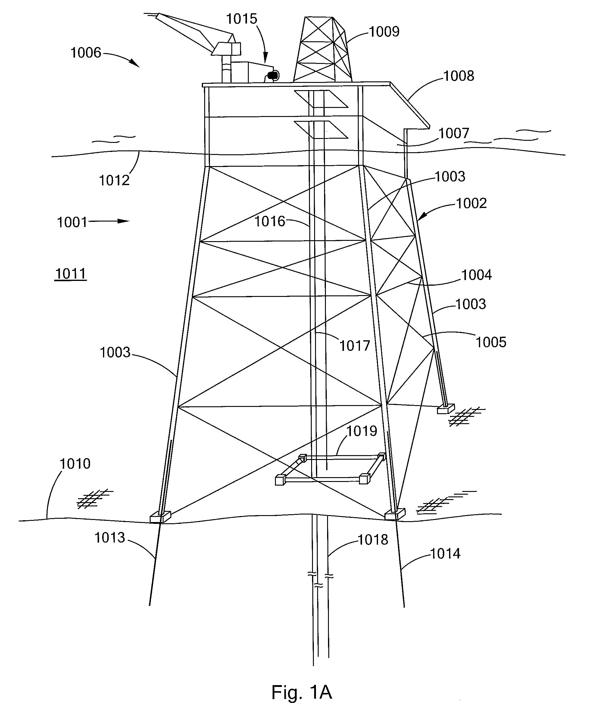
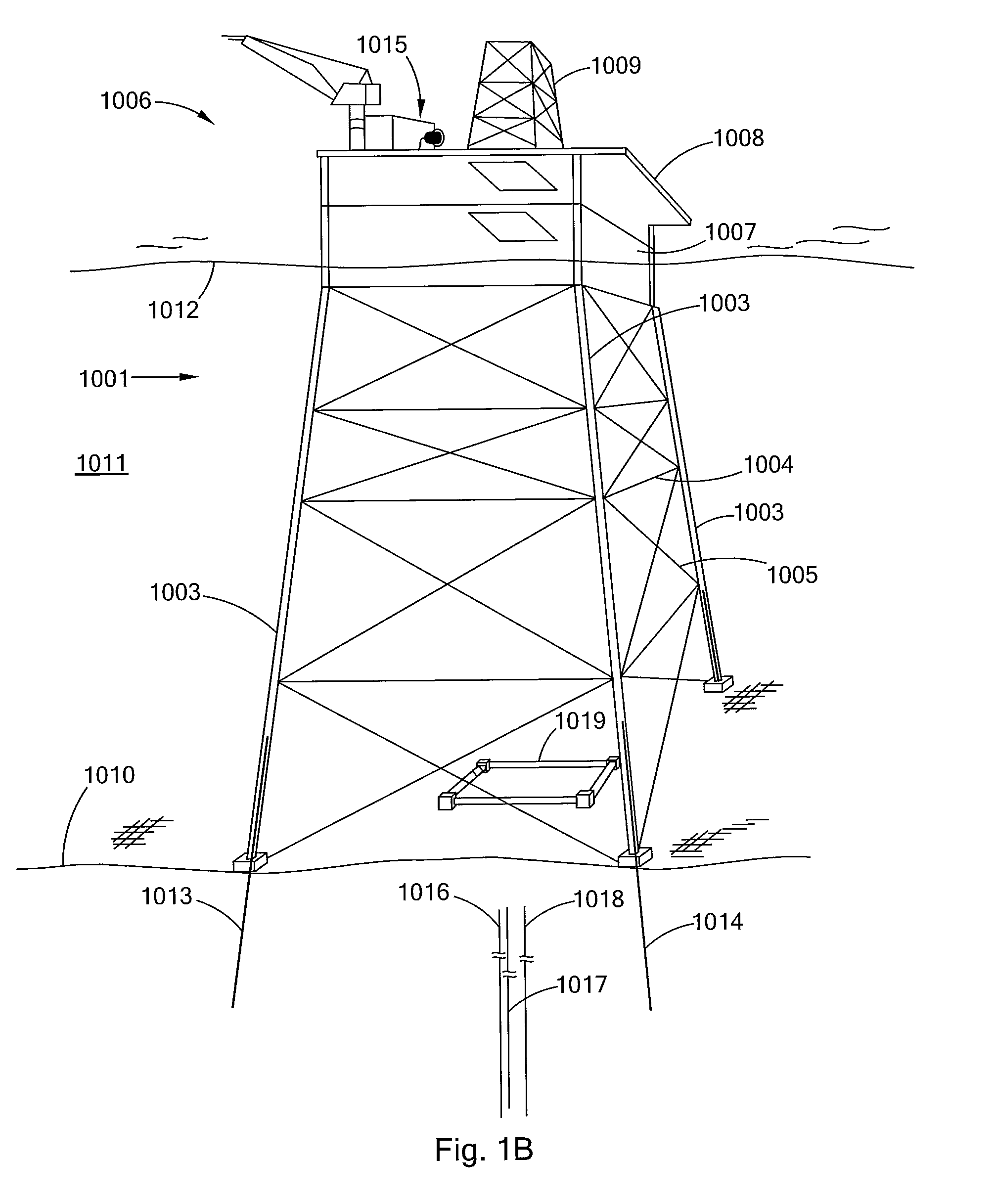
[0240]In this example a laser removal system may be used to assist in the plugging abandonment and decommission of a subsea field. The field is associated with a floating spar platform. Two mobile containers are transported to the spar platform, containing a laser module, and a work container have laser cutting tools, devices, umbilicals and other support materials. The laser module obtains its power from the spar platform's power generators or supplied power generation. The laser cutting tools are lowered by the spars hoisting equipment, to the seafloor, where they are lowered into a first well that has been plugged, the laser tool directs a high power laser beam, having about 10 kW of power, in an air jet, around the interior of the well. The laser beam and jet in a single pass severs all of the tubulars in the well at about 15 feet below the mud line. This process is repeated for the remaining wells in the field that are to be abandoned.


PUM

PropertyMeasurementUnit
poweraaaaaaaaaa
weightaaaaaaaaaa
weightaaaaaaaaaa

Abstract

There is provided high power laser systems, high power laser tools, and methods of using these tools and systems for cutting, sectioning and removing structures objects, and materials, and in particular, for doing so in difficult to access locations and environments, such as offshore, underwater, or in hazardous environments, such as nuclear and chemical facilities. Thus, there is also provided high power laser systems, high power laser tools, and methods of using these systems and tools for removing structures, objects, and materials located offshore, under bodies of water and under the seafloor.

Description

[0001]This application: (i) claims, under 35 U.S.C. §119(e)(1), the benefit of the filing date of Aug. 2, 2011 of provisional application Ser. No. 61 / 514,391; (ii) claims, under 35 U.S.C. §119(e)(1), the benefit of the filing date of Mar. 1, 2012 of provisional application Ser. No. 61 / 605,422; (iii) claims, under 35 U.S.C. §119(e)(1), the benefit of the filing date of Mar. 1, 2012 of provisional application Ser. No. 61 / 605,429; (iv) claims, under 35 U.S.C. §119(e)(1), the benefit of the filing date of Mar. 1, 2012 of provisional application Ser. No. 61 / 605,434; (v) is a continuation-in-part of U.S. patent application Ser. No. 13 / 222,931, filed Aug. 31, 2011, which claims, under 35 U.S.C. §119(e)(1), the benefit of the filing date of Aug. 31, 2010 of provisional application number Ser. No. 61 / 378,910; (vi) is a continuation-in-part of U.S. patent application Ser. No. 13 / 211,729, filed Aug. 17, 2011, which claims, under 35 U.S.C. §119(e)(1), the benefit of the filing date of Aug. 17, ...

Claims


Application Information

Patent Timeline
Patent Type & Authority Applications(United States)
IPC IPC(8): B23K26/12B63B35/28E21B33/13B23K26/00B23K26/38
CPCB23K26/121B23K26/0096B63B35/28E21B33/13B23K26/38B08B7/0042B23K26/0652B23K26/106B23K26/127B23K26/1464E21B29/02E21B19/002E02B2017/0052B23K26/064B23K26/146B23K26/1224B23K2103/10B63B35/00B23K26/00B23K26/04B23K26/12B23K26/14B63B17/00B63B19/00B63B21/00E02D17/00
Inventor ZEDIKER, MARK S.GRUBB, DARYL L.DE WITT, RONALD A.DEUTCH, PAUL D.MOXLEY, JOEL F.MARSHALL, SCOTT A.LINYAEV, EUGENE J.SCHROIT, SAM N.KOLACHALAM, SHARATH K.
Owner FORO ENERGY
Why Eureka
Try Eureka