Pulling grip for installing pre-connectorized fiber optic cable

Active Publication Date: 2005-05-26
CORNING OPTICAL COMM LLC
View PDF6 Cites 40 Cited by
  • Summary
  • Abstract
  • Description
  • Claims
  • Application Information

AI Technical Summary

Benefits of technology

[0007] The above described problems and deficiencies associated with the known pulling grips for installing a pre-connectorized fiber optic cable are overcome by a pulling grip according to the present invention. In particular, the invention provides a pulling grip for installing a pre-connectorized fiber optic cable that includes a pulling grip housing and a pulling grip sleeve that do not remain on the fiber optic cable after installation, and thus do not take up any of the available volume under a raised floor. Further, the pulling grip housing is not time consuming or labor intensive to load, securely retains the fiber optic connectors and the furcation plug during installation, and does not snag the fiber optic connectors when removed. The pulling grip housing

Problems solved by technology

Furthermore, the pulling grip does not utilize a pulling grip sleeve made of a mesh material that cont

Method used


Image

  • Pulling grip for installing pre-connectorized fiber optic cable
  • Pulling grip for installing pre-connectorized fiber optic cable
  • Pulling grip for installing pre-connectorized fiber optic cable

Examples


Embodiment Construction

[0031] The present invention will be described more fully hereinafter with reference to the accompanying drawings, in which exemplary embodiments of the invention are shown, including the embodiment presently contemplated by the inventors as being the best mode for practicing the invention. The invention may, however, be embodied in many different forms and should not be construed as being limited to the embodiments set forth herein. Instead, these exemplary embodiments are shown and described so that this disclosure will be thorough and complete, and will fully convey the scope of the invention to those skilled in the art. Like reference numbers refer to like elements throughout the detailed description and the various drawings.

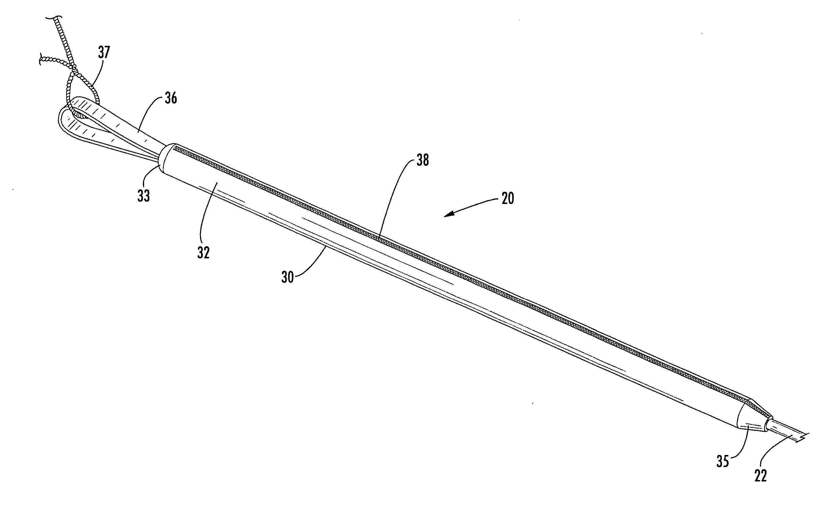
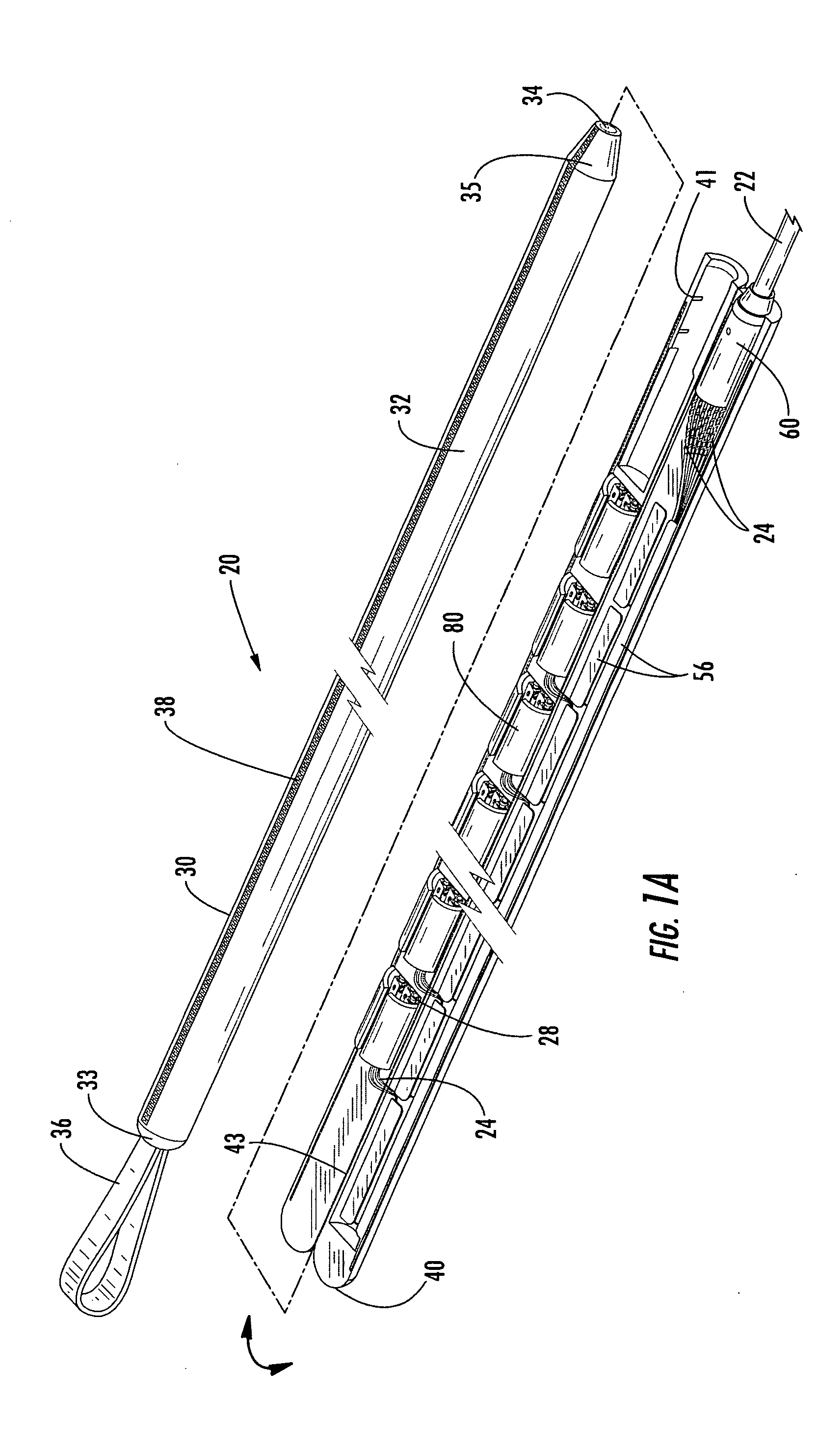
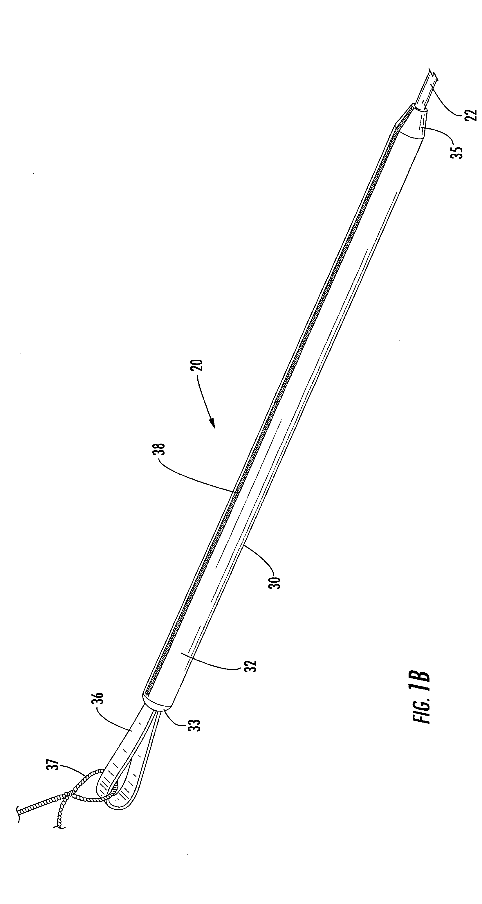
[0032] Referring now to the accompanying drawings, FIGS. 1A, 1B, 2A and 2B show a pulling grip, indicated generally at 20, according to an exemplary embodiment of the present invention. The illustrated embodiment of the pulling grip 20 comprises a pulling g...


PUM


Abstract

A pulling grip includes a pulling grip sleeve, a pulling grip housing and a furcation plug attached to the terminated end of a fiber optic cable. The pulling sleeve includes a bag adapted to be positioned over the pulling grip housing and the furcation plug and to be opened and closed by a lengthwise extending zipper. The pulling grip housing has a first compartment defining an elongate channel for routing optical fibers of the fiber optic cable and a second compartment defining a plurality of pockets that each store a plurality of fiber optic connectors mounted upon the ends of the optical fibers. The pulling grip housing may be formed as a plurality of injection molded modules to increase rigidity and to reduce manufacturing cost. The furcation plug includes means for readily integrating the furcation plug with a conventional distribution frame or rack, or with a cross-connect housing.

Description

FIELD OF THE INVENTION [0001] The present invention relates generally to a device for installing a fiber optic cable, and more particularly, to a pulling grip for installing a pre-connectorized fiber optic cable through a small diameter conduit or under a raised floor. BACKGROUND OF THE INVENTION [0002] In many instances, a pre-connectorized fiber optic cable, such as a trunk cable serving a data center in an office building, must be installed through a small diameter conduit or under a raised floor to satisfy space and aesthetic requirements. As used herein, the term “pre-connectorized fiber optic cable” refers to a communications cable including at least one optical fiber that is terminated to a fiber optic connector prior to installing the fiber optic cable at a service location, commonly referred to as a “customer premises.” Typically, the fiber optic cable is manufactured to a predetermined length and one or more optical fibers are terminated to respective fiber optic connector...

Claims


Application Information

Patent Timeline
IPC IPC(8): G02B6/38G02B6/44
CPCG02B6/4455G02B6/3897G02B6/4471G02B6/545
Inventor COOKE, TERRY L.JOHNSON, JOHN B.
Owner CORNING OPTICAL COMM LLC
Why Eureka
Try Eureka