Method and apparatus for compression molding fiber reinforced thermoplastic parts

a technology of thermoplastic parts and compression molding, which is applied in the direction of weight reduction, etc., can solve the problems of time-consuming, labor-intensive and labor-intensive composite laminate fabrication process described above, and the inability to integrate part features, so as to reduce or eliminate the effect of touch labor required parts for fabrication and reduced total part weigh

Active Publication Date: 2016-03-15
THE BOEING CO
View PDF64 Cites 0 Cited by
  • Summary
  • Abstract
  • Description
  • Claims
  • Application Information

AI Technical Summary

Benefits of technology

[0009]The disclosed embodiments provide a method and apparatus for producing composite parts using compression molding of thermoplastic resins reinforced with discontinuous fibers. Composite parts having contours, curves and / or complex geometries can be fabricated without the need for vacuum bagging and autoclave processing. Fittings can be integrated into the parts, thereby reducing or eliminating the need to separately fabricate and attach the fittings to the parts. The touch labor required part for fabrication is reduced, and total part weight may be decreased. Parts with complex geometries can be fabricated more quickly and economically using relatively inexpensive molding equipment. Reinforced thermoplastic parts having a high content of discontinuous fibers may be molded inexpensively, and without substantially damaging the fibers during the molding process. Long resin flow distances may be achieved to permit molding complex part features at any point along the length of the part. Elongated reinforced thermoplastic parts having cross-sections that vary in geometry along their length, including changes in size, thickness and curvature are made possible.

Problems solved by technology

The composite laminate fabrication process described above is time-consuming, labor intensive and requires expensive capital equipment such as automatic fiber placement machines.
Moreover, these composite laminate parts may be heavier than desired because pad-ups required for localized strengthening must be formed gradually, thus requiring placement of the of additional ply materials.
Thermoplastic parts having discontinuous fiber reinforcement may be molded into a variety of shapes, however the ability to integrate part features is limited due to the high viscosity of the melted thermoplastic resin which limits resin flow.
The ability to flow resins is particularly limited where the reinforcement fibers are relatively long, the fiber content is high, and the required flow distances are long.
Also, molding techniques such as injection molding may have a tendency to damage the fibers, thereby affecting the strength of the molded part.
Other molding techniques, such as extrusion molding are limited to producing a single, straight part having a uniform cross-sectional shape.

Method used


Image

  • Method and apparatus for compression molding fiber reinforced thermoplastic parts
  • Method and apparatus for compression molding fiber reinforced thermoplastic parts
  • Method and apparatus for compression molding fiber reinforced thermoplastic parts

Examples


Embodiment Construction

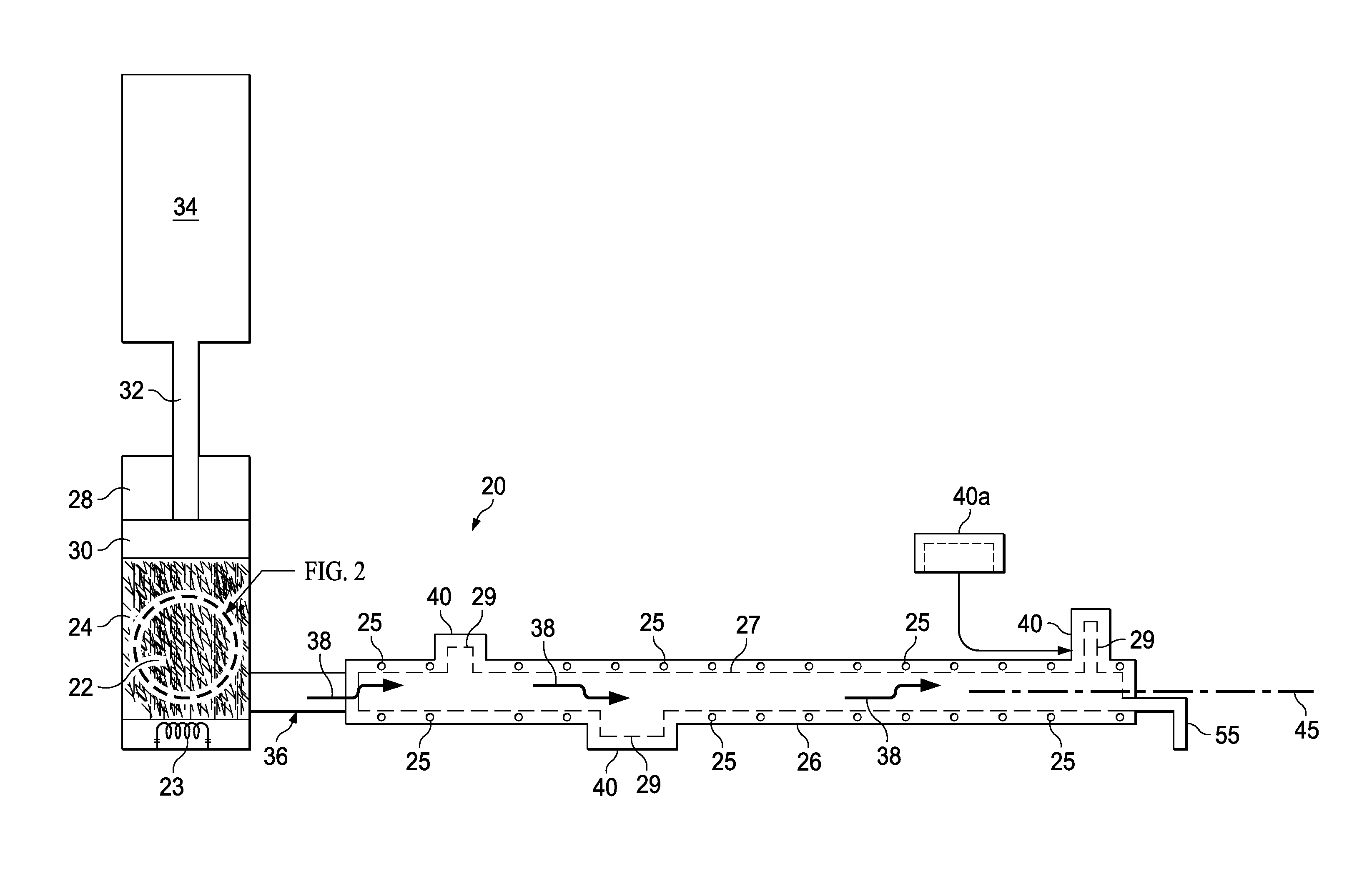
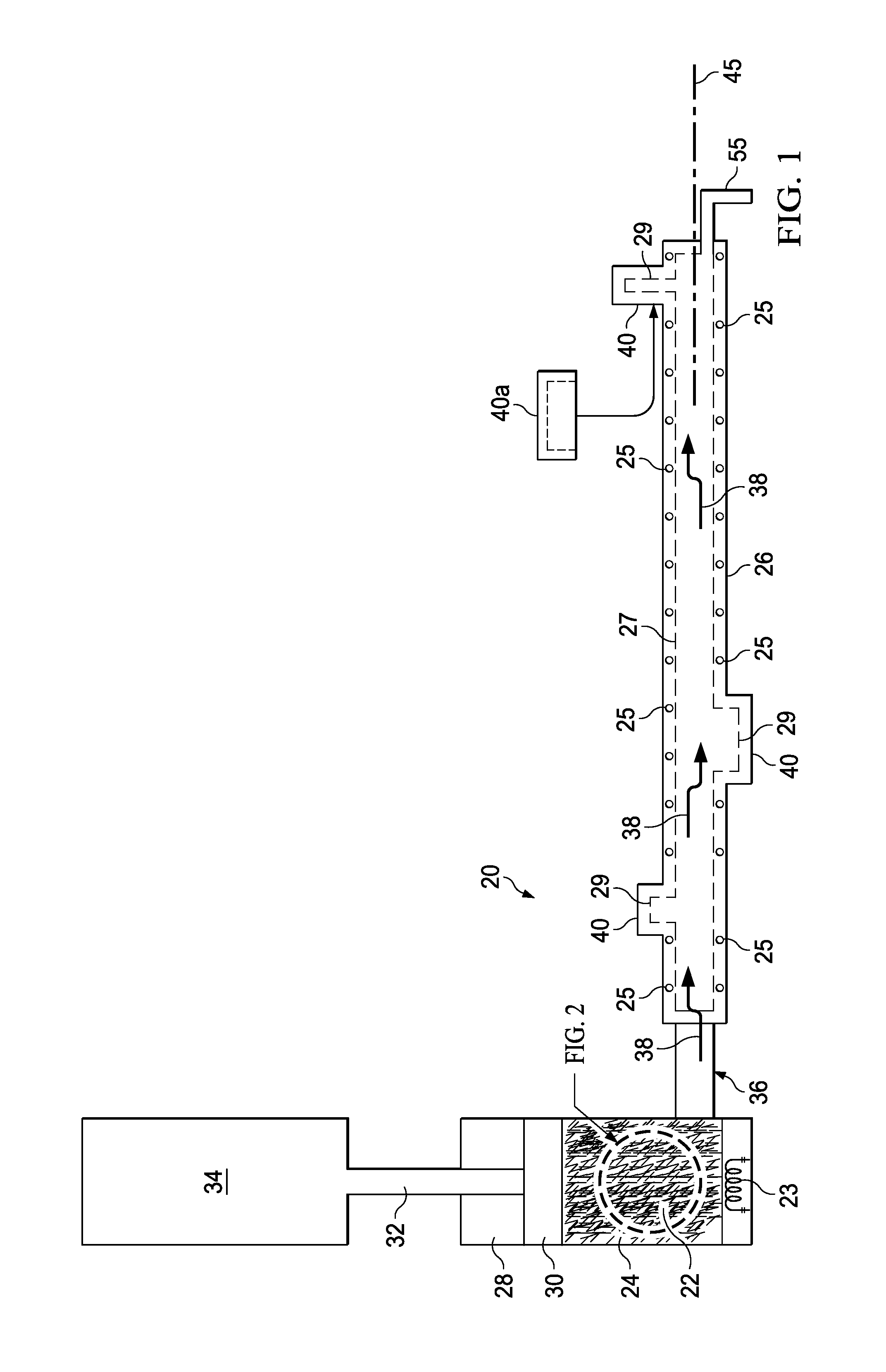
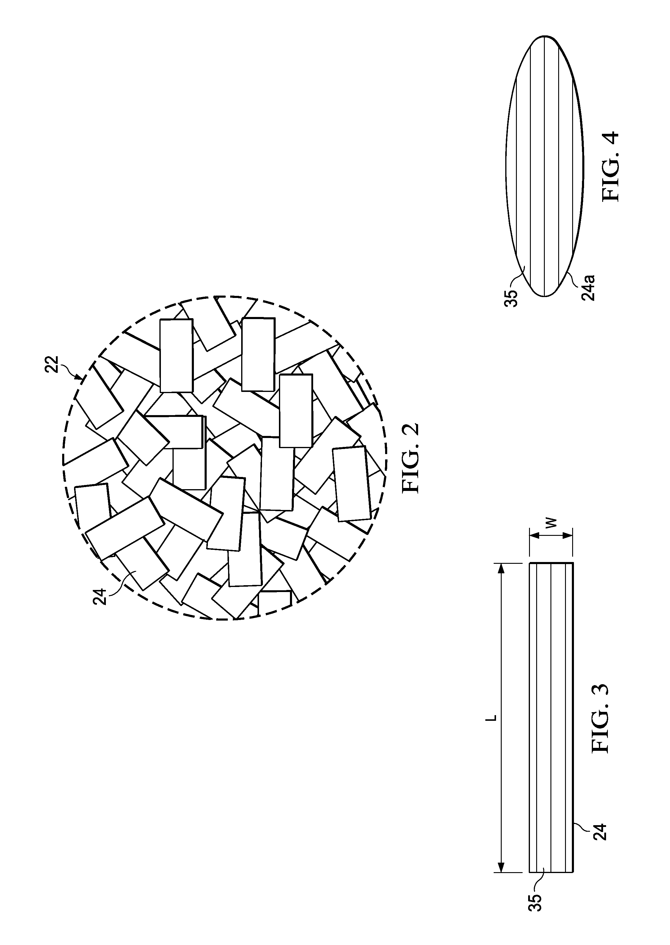
[0032]Referring to FIGS. 1 and 2, the disclosed embodiments relate to apparatus 20 for compression molding any of a variety of elongated thermoplastic resin parts 42 (FIGS. 5-8) that are reinforced with discontinuous fibers. The apparatus 20 broadly includes an elongate mold tool 26 and a charge cylinder 28 adapted to hold a charge 22 comprising a quantity of thermoplastic composite (TPC) flakes 24 that have been pre-consolidated. As used herein, “flakes”“TPC flakes” and “fiber flakes” refer to individual pieces, fragments, slices, layers or masses of thermoplastic resin that contain fibers suitable for reinforcing a part 42. An actuator 34, which may comprise, without limitation, a hydraulic motor, is coupled by a ram rod 32 with a piston 30 within the charge cylinder 28. The charge cylinder 28 may be coupled with one end of the mold tool 26 by an injection port 36 to permit a melted charge 22 to be injected into a mold part cavity 27 in the mold tool 26. In other embodiments, disc...


PUM

PropertyMeasurementUnit
lengthsaaaaaaaaaa
lengthsaaaaaaaaaa
lengthaaaaaaaaaa

Abstract

A fiber reinforced thermoplastic part with integral fittings is compression molded. A slug of pre-consolidated, fiber reinforced thermoplastic is heated until flowable and then injected into a mold tool to form both the part and the fitting.

Description

CROSS REFERENCE TO RELATED APPLICATIONS[0001]This application is related to co-pending U.S. patent application Ser. No. 14 / 095,531, filed concurrently herewith on Dec. 3, 2013, and co-pending U.S. patent application Ser. No. 14 / 095,693, filed concurrently herewith on Dec. 3, 2013, both of which applications are incorporated by reference herein in their entireties.BACKGROUND INFORMATION[0002]1. Field[0003]The present disclosure generally relates to the fabrication of fiber reinforced thermoplastic parts, and deals more particularly with a method and apparatus for compression molding such parts, especially those having complex shapes.[0004]2. Background[0005]In the aircraft and other industries, a variety of parts and structures are fabricated from composites or combination of composites and light weight metals because of their relatively high strength-to-weight ratios. In the case of parts having contours or relatively complex geometries, the parts are often fabricated using thermose...

Claims


Application Information

Patent Timeline
Patent Type & Authority Patents(United States)
IPC IPC(8): B29C45/72B29C43/52B29B11/12B29C43/00B29C43/36B29K105/12
CPCB29C45/72B29B11/12B29C43/003B29C43/52B29C2043/3628B29K2105/12B29C43/22B29C45/73B29C45/74B29C70/42B29C70/081B29C70/12B29C70/46
Inventor FISHER, JR., EDWARD, M.
Owner THE BOEING CO
Why Eureka
Try Eureka