Liquid-cooled cabinet manifold and liquid-cooled cabinet

a liquid-cooled cabinet and manifold technology, applied in the field of liquid-cooled cabinets, can solve the problems of increasing the computing power of the underlying hardware infrastructure, increasing the power consumption of servers, and significant increases in overall power consumption and heat generation

Pending Publication Date: 2022-10-06
SQ TECH (SHANGHAI) CORP +1
View PDF0 Cites 2 Cited by
  • Summary
  • Abstract
  • Description
  • Claims
  • Application Information

AI Technical Summary

Benefits of technology

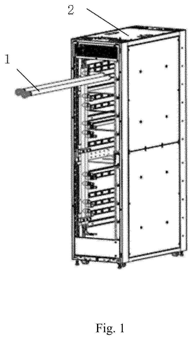
[0006]It is an object of the present invention to provide a liquid-cooled cabinet manifold and a liquid-cooled cabinet, which can satisfy the heat dissipation requirements of existing standard cabinets.
[0030]Compared with the prior art, the present invention has the following beneficial effects:
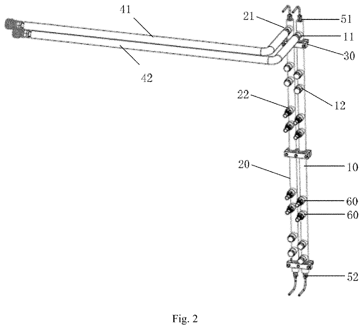
[0032]2. Two exhaust valves are provided respectively at one end of the main inlet pipe and one end of the main outlet pipe, and two drain valves are provided respectively at the other end of the main inlet pipe and the other end of the main outlet pipe. The main inlet pipe is oriented so that one end is located above the other end thereof. As such, the exhaust valves are arranged at the top of the main inlet and outlet pipes, allowing easy release of air in the manifold and depressurization thereof. Moreover, the drain valves are arranged at the bottom of the main inlet and outlet pipes to discharge impurities accumulated there, preventing damage to delicate structures of quick-connect connectors on the liquid-cooling pipes and of cold plates.
[0033]3. Both the main inlet and outlet pipes are made of a PVDF polymer. Compared with conventional stainless steel pipes, such polymer pipes can be more easily manufactured using a cheaper mold, have a lighter weight, and allow easier assembly, operation and maintenance.
[0034]4. The branch inlet and outlet ports are both provided with a first quick-connect connector, and the supply and return ports are both provided with a second quick-connect connector. The first quick-connect connector at the branch inlet port is connected to the second quick-connect connector at the supply ports, and the first quick-connect connector at the branch outlet port is connected to the second quick-connect connector at the return port. The first quick-connect connectors are male quick-connect connectors, and the second quick-connect connectors are female quick-connect connectors. The first quick-connect connectors can be mated and unmated by a single hand. The quick-connect connector at the branch inlet port is provided with a first identifier, and the quick-connect connector at the branch outlet port is provided with a second identifier. The first and second identifiers are adapted to distinguish the branch inlet port from the branch outlet port, facilitating subsequent operation and maintenance.

Problems solved by technology

With the vigorous development of computing platforms, practical services are imposing increasingly demanding requirements on the computing power of the underlying hardware infrastructure.
Advancements in performance simply lead to increasing power consumption of servers.
Meanwhile, along with rising of computing power, process upgrades also bring about significant increases in overall power consumption and heat generation.
Given a fixed number of servers per cabinet, significant increases in overall power consumption of cabinets bring great challenges to energy consumption and heat exchange of data centers.
The traditional air-cooling mode is gradually approaching its capacity limit and falls short in meeting the requirements of high-power computing chips.
Although water cooling systems require dedicated cabinets and are associated with high structural complexity, high cost and very high maintenance complexity, they can satisfy the cooling and energy saving requirements of large data centers.

Method used


Image

  • Liquid-cooled cabinet manifold and liquid-cooled cabinet
  • Liquid-cooled cabinet manifold and liquid-cooled cabinet
  • Liquid-cooled cabinet manifold and liquid-cooled cabinet

Examples


Embodiment Construction

[0044]The Liquid-cooled cabinet manifold and liquid-cooled cabinet of the present invention will be described in greater detail below with reference to the accompanying drawings, which present a preferred embodiment of the invention. It would be appreciated that those skilled in the art can make changes to the invention disclosed herein while still obtaining the beneficial results thereof. Therefore, the following description shall be construed as being intended to be widely known by those skilled in the art rather than as limiting the invention.

[0045]For the sake of clarity, not all features of an actual implementation are described in this specification. In the following, description and details of well-known functions and structures are omitted to avoid unnecessarily obscuring the invention. It should be appreciated that in the development of any such actual implementation, numerous implementation-specific decisions must be made to achieve specific goals of the developers, such a...


PUM


Abstract

A liquid-cooled cabinet manifold and a liquid-cooled cabinet are disclosed. The liquid-cooled cabinet manifold includes a main inlet pipe and a main outlet pipe, which are arranged in parallel to and spaced apart from each other. The main inlet pipe has a main inlet port and a branch inlet port, and the main outlet pipe has a main outlet port and a branch outlet port. The branch inlet port is staggered from the branch outlet port along the direction of extension of the main inlet pipe, and an angle is formed between the branch inlet port and the branch outlet port. The branch inlet port and the branch outlet port form a pair connected to an object to be cooled in the liquid-cooled cabinet. When a server with a large depth is accommodated in the cabinet, the angle can be adjusted to ensure a minimized radius of flexure of supply and return pipes.

Description

CROSS-REFERENCE TO RELATED APPLICATION[0001]This application claims the priority of Chinese patent application number 202210344072.2, filed on Mar. 31, 2022, the entire contents of which are incorporated herein by reference.TECHNICAL FIELD[0002]The present invention relates to the field of liquid-cooled cabinets and, more specifically, to a liquid-cooled cabinet manifold and a liquid-cooled cabinet.BACKGROUND[0003]With the vigorous development of computing platforms, practical services are imposing increasingly demanding requirements on the computing power of the underlying hardware infrastructure. Advancements in performance simply lead to increasing power consumption of servers. Meanwhile, along with rising of computing power, process upgrades also bring about significant increases in overall power consumption and heat generation. Given a fixed number of servers per cabinet, significant increases in overall power consumption of cabinets bring great challenges to energy consumption...

Claims


Application Information

Patent Timeline
Patent Type & Authority Applications(United States)
IPC IPC(8): H05K7/20F28F9/02F16L3/10
CPCH05K7/20272F28F9/0243F28F9/0258F16L3/10H05K7/20781F16L3/237F16L3/2235
Inventor GENG, ZHAOTIAN, GUANGZHAO
Owner SQ TECH (SHANGHAI) CORP
Why Eureka
Try Eureka