Heat conducting structure, manufacturing method thereof, and mobile device

a technology of conducting structure and heating element, which is applied in the direction of laminated elements, lighting and heating apparatus, and semiconductor/solid-state device details. it can solve the problems of narrow space inside the mobile device for installing various electronic components, permanent damage to the component or the mobile device, etc., to accelerate the circulation efficiency of working fluid, increase the hydrophilicity of metal microstructure, and increase the reflux rate

Inactive Publication Date: 2020-12-31
CTRON ADVANCED MATERIAL CO LTD
View PDF6 Cites 2 Cited by
  • Summary
  • Abstract
  • Description
  • Claims
  • Application Information

AI Technical Summary

Benefits of technology

[0024]As mentioned above, in the heat conducting structure, the manufacturing method thereof, and the mobile device of this disclosure, the first heat conducting layer and the second heat conducting layer are disposed at two sides of the metal microstructure inside the heat conducting structure. This configuration can increase the hydrophilicity of the metal microstructure so as to increase the reflux rate of the liquid working fluid at the metal microstructure, thereby accelerating the circulation efficiency of the working fluid, and improving the temperature uniform effect and heat conduction effect of the heat conducting structure. In addition, since the total thickness of the first heat conducting layer and the second heat conducting layer adjacent to the heat source end is greater than the total thickness of the first heat conducting layer and the second heat conducting layer away from the ...

Problems solved by technology

If the heat is not properly dissipated to the outside, it may cause permanent damage to the component or the mobile device.
In addition, as...

Method used


Image

  • Heat conducting structure, manufacturing method thereof, and mobile device
  • Heat conducting structure, manufacturing method thereof, and mobile device
  • Heat conducting structure, manufacturing method thereof, and mobile device

Examples


Embodiment Construction

[0038]The present disclosure will be apparent from the following detailed description, which proceeds with reference to the accompanying drawings, wherein the same references relate to the same elements.

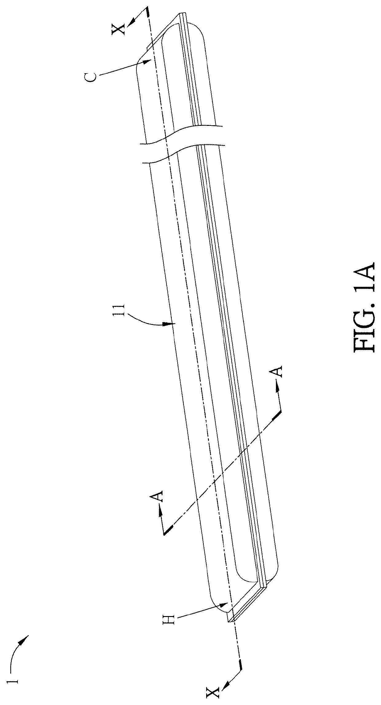
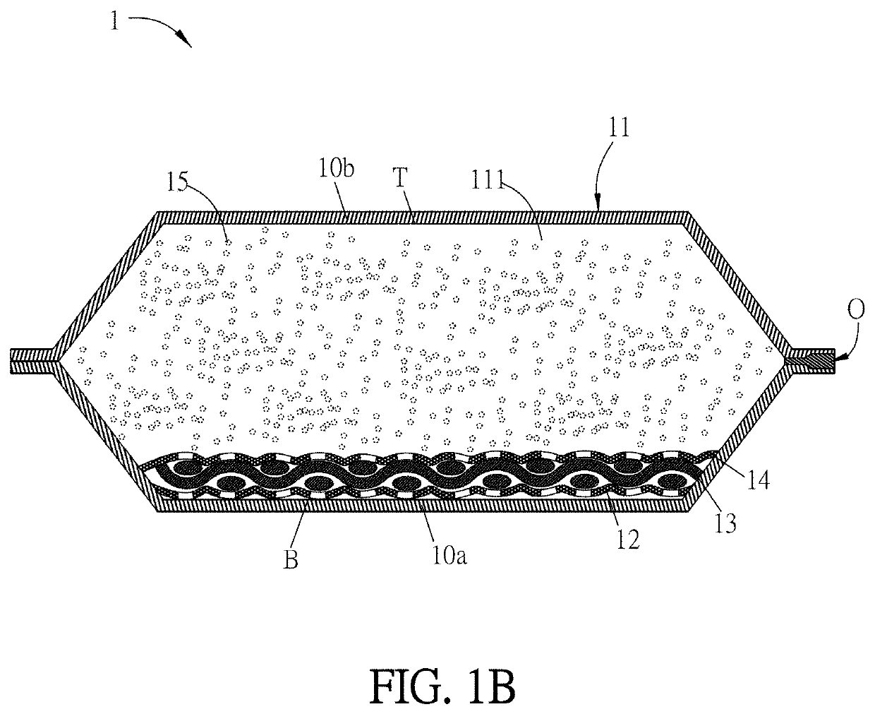
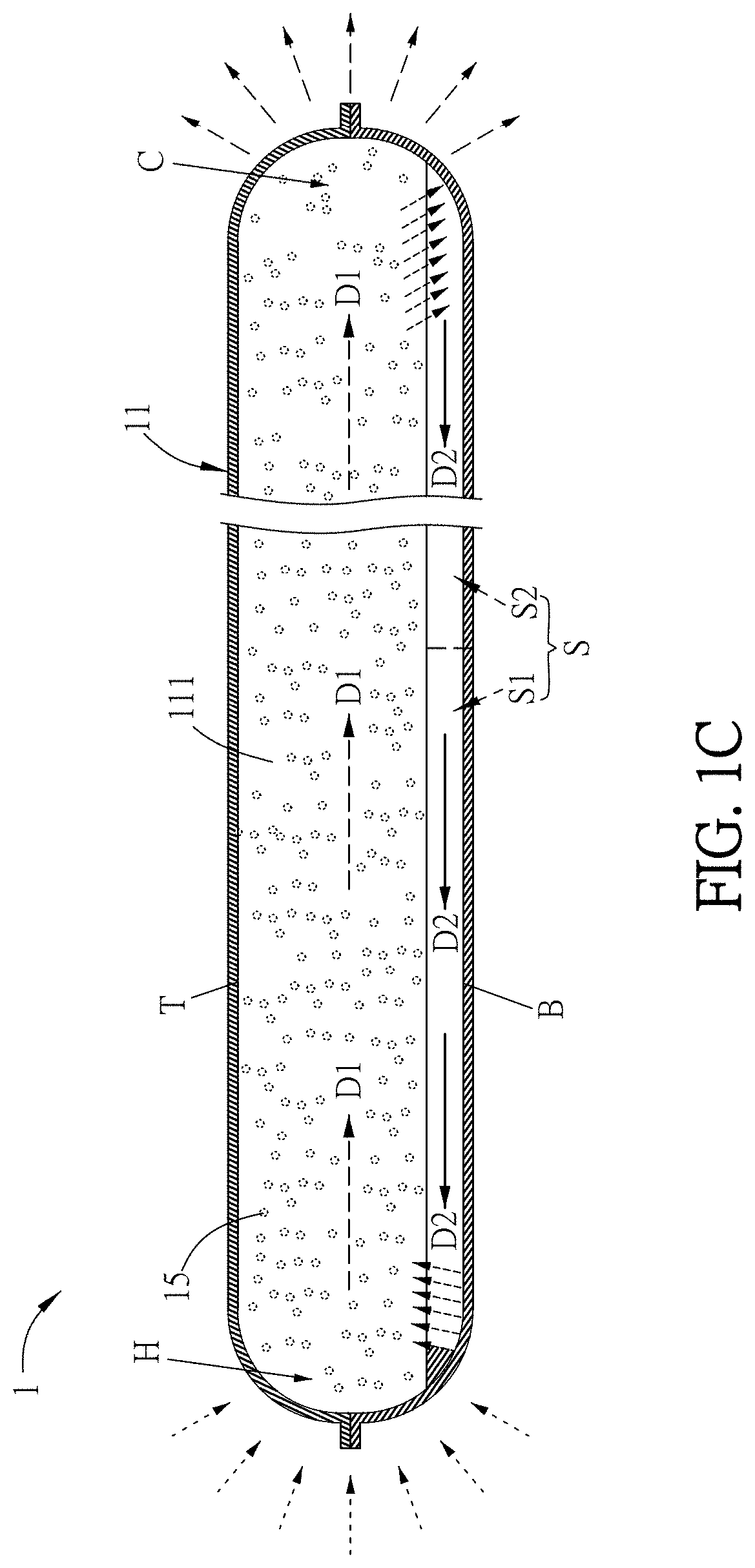
[0039]The heat conducting structure of the present disclosure can have higher heat conducting efficiency, thereby rapidly dissipating the heat energy generated by the heat source and satisfy the heat dissipation requirement of the thin and light mobile device. The heat conducting structure can be disposed inside the mobile device, and one end thereof contacts the heat source to conduct the heat energy generated by the heat source to the other end thereof through the heat conducting structure, thereby preventing the crash or burn of the mobile device caused by the high temperature of the heat source. In some embodiments, the heat source can be, for example but not limited to, a central processing unit (CPU), a memory chip (card), a display chip (card), a panel, or a power component in...


PUM


Abstract

A heat conducting structure comprises a heat conducting unit, a first heat conducting layer, a metal microstructure, a second heat conducting layer and a working fluid. The heat conducting unit forms a closed chamber having opposite bottom surface and top surface. Opposite ends of the heat conducting unit are functioned as a heat source end and a cooling end, respectively. The first heat conducting layer is disposed on the bottom surface and/or the top surface of the closed chamber. The metal microstructure is disposed on the first heat conducting layer. The second heat conducting layer is disposed at one side of the metal microstructure. The total thickness of the first and second heat conducting layers adjacent to the heat source end is greater than the total thickness thereof away from the heat source end. A manufacturing method of the heat conducting structure and a mobile device are disclosed.

Description

CROSS REFERENCE TO RELATED APPLICATIONS[0001]This Non-provisional application claims priority under 35 U.S.C. § 119(a) on Patent Application No(s). 108123019 filed in Taiwan, Republic of China on Jun. 28, 2019, the entire contents of which are hereby incorporated by reference.BACKGROUNDTechnology Field[0002]The present disclosure relates to a heat conducting structure, a manufacturing method thereof, and a mobile device having the heat conducting structure.Description of Related Art[0003]With the progress of technology, the design and development of mobile devices are mostly focused on the thinning and high performance of the products. In the case of high-speed calculation and thinning, the computing chip (such as CPU) inside the mobile device must also provide high-efficiency execution speed, and definitely generate extremely high heat (even over 100° C.). If the heat is not properly dissipated to the outside, it may cause permanent damage to the component or the mobile device.[000...

Claims


Application Information

Patent Timeline
IPC IPC(8): H05K7/20F28D15/04
CPCH05K7/20336H05K7/20309H04M1/0202F28D15/046H05K7/20318H05K7/20445H01L23/367H01L23/3736H01L23/373H01L23/473F28D15/0233F28F3/12F28D2021/0029
Inventor SHIAU, YI-HAU
Owner CTRON ADVANCED MATERIAL CO LTD
Why Eureka
Try Eureka