Liquid cooling system for cabinet server

a liquid cooling system and cabinet server technology, applied in the direction of cooling/ventilation/heating modifications, electrical apparatus, electrical apparatus contruction details, etc., can solve the problems of affecting the design and application of server design and application, affecting the performance improvement of computer systems, and affecting the cooling effect of the server, so as to achieve the effect of less space, good cooling capacity and good energy-efficiency ratio of the liquid cooling system

Inactive Publication Date: 2019-11-07
INVENTEC PUDONG TECH CORPOARTION +1
View PDF8 Cites 3 Cited by
  • Summary
  • Abstract
  • Description
  • Claims
  • Application Information

AI Technical Summary

Benefits of technology

[0008]In the embodiment of the present disclosure, the cabinet server is cooled by the liquid cooling method, and the energy-efficiency ratio of the liquid cooling system is less than 1.3, there is almost no noise, no low filling water temperature is needed, the natural cold source is fully utilized, and the cooling tower can be used to meet the heat dissipation requirement. This disclosure uses liquid cooling to replace the air conditioning system, and the liquid cooling system occupies less space in the cabinet server, so that the cabinet server can accommodate more servers. The liquid cooling system of the present disclosure has a good cooling capacity, improves the heat flux density of the data center of the machine, saves the floor space, and is not restricted by altitude and geography, and can work normally anywhere.

Problems solved by technology

From the perspective of cooling, the main energy consumption of air-cooling is generated by air-cooled outdoor condensers, air conditioners, compressors, etc., resulting in a relatively low energy efficiency of the stand-alone system.
Conventional air-cooling and heat-dissipating technology is relatively mature, and the energy consumption and noise problem brought by the fan of the air-cooling system have seriously hindered the improvement of computer performance.
In addition, for high-performance servers, due to the increased power consumption of CPUs / DIMMs and the introduction of expansion cards with strong computing and storage performance, heat dissipation has become a significant challenge for server design and application.
For ultra-high power density data centers, air-cooling technology is difficult to achieve efficient heat dissipation.

Method used


Image

  • Liquid cooling system for cabinet server
  • Liquid cooling system for cabinet server
  • Liquid cooling system for cabinet server

Examples


Embodiment Construction

[0017]In the following detailed description, for purposes of explanation, numerous specific details are set forth in order to provide a thorough understanding of the disclosed embodiments. It will be apparent, however, that one or more embodiments may be practiced without these specific details. In other instances, well-known structures and devices are schematically shown in order to simplify the drawings.

[0018]The use of “first”, “second”, etc., as used herein, does not specifically mean the order, and is not intended to limit the disclosure, but merely to distinguish components or operations described in the same technical terms.

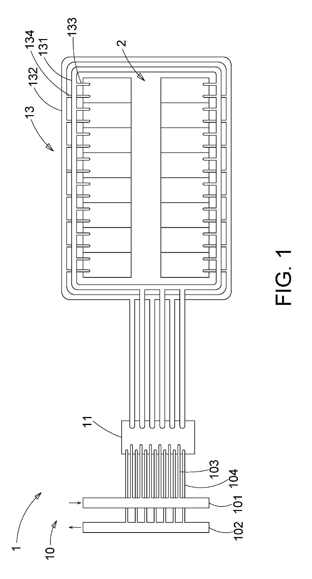
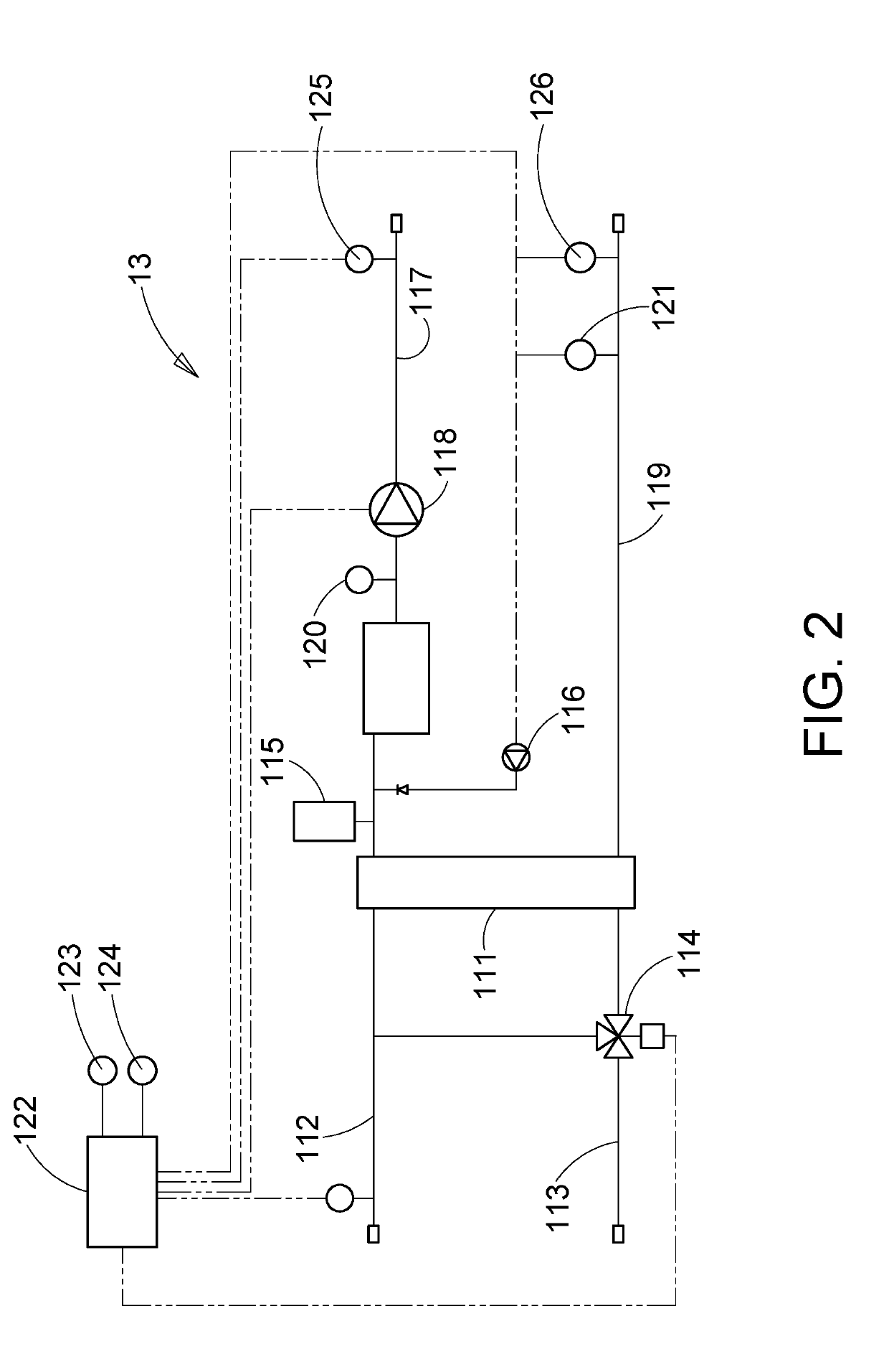
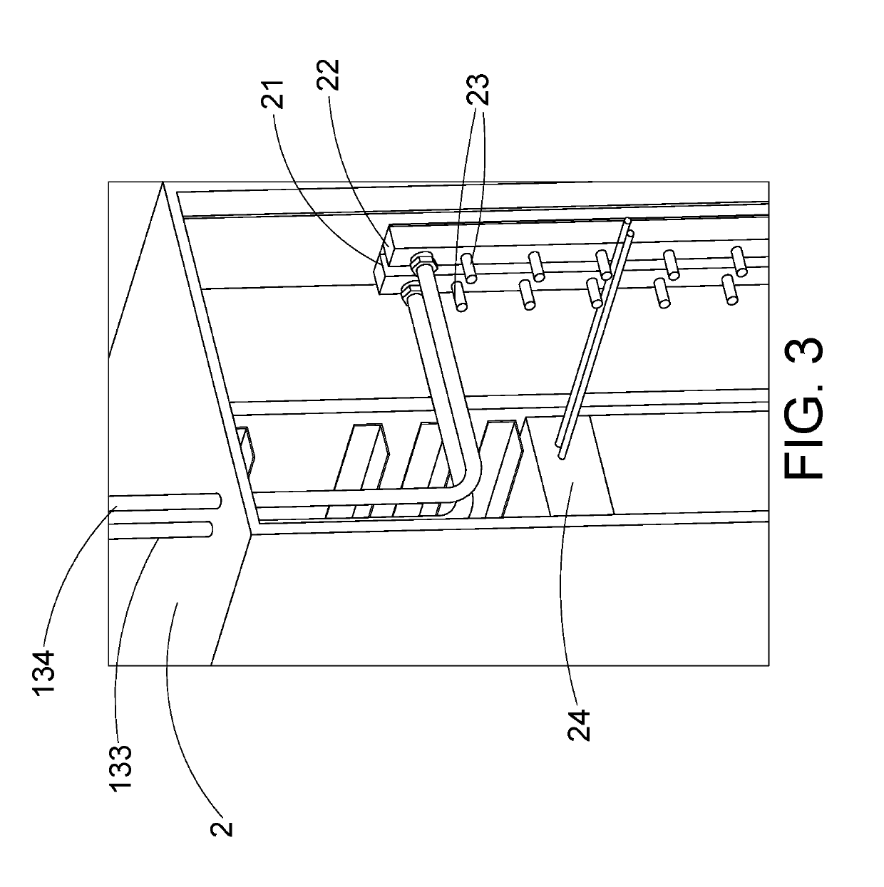
[0019]Please refer to FIG. 1, which is a schematic diagram of a liquid cooling system according to an embodiment of the present disclosure. As shown in the figure, the present embodiment provides a liquid cooling system 1 for a cabinet server, and the liquid cooling system 1 includes a primary side liquid circulation pipe 10, the distribution control devic...


PUM


Abstract

The present application discloses a liquid cooling system for a cabinet server, which includes a primary side liquid circulation pipe, a distribution control device, and a secondary side liquid circulation pipe, and the primary side liquid circulation pipe is connected to the water filling device. The distribution control device is connected to the primary side liquid circulation pipe, and the secondary side liquid circulation pipe is connected to the distribution control device and at least one cabinet server. The liquid cooling system of the present application cools the cabinet server by liquid cooling, and the energy efficiency ratio of the liquid cooling system is below 1.3, there is almost no noise, no low filling water temperature is needed, natural cooling source is fully utilized, and the cooling tower can be used to meet the heat dissipation requirement.

Description

RELATED APPLICATIONS[0001]This application claims priority to China Application CN201810420096.5, filed on May 4, 2018, which is incorporated by reference herein in its entirety.BACKGROUNDTechnical Field[0002]The present disclosure relates to the technical field of cabinet server systems, and more particularly to a liquid cooling system for a cabinet server.Related Art[0003]At present, most of the data centers use air-cooled air conditioning systems to dissipate heat from the cabinet servers. The air-cooled air conditioning system uses the rotation of the fans to drive air flow, to take away the heat of the cabinet servers. From the perspective of cooling, the main energy consumption of air-cooling is generated by air-cooled outdoor condensers, air conditioners, compressors, etc., resulting in a relatively low energy efficiency of the stand-alone system. Currently, the power usage effectiveness (PUE) commonly used air-cooling method is about 1.5-2.0.[0004]Conventional air-cooling an...

Claims


Application Information

Patent Timeline
Patent Type & Authority Applications(United States)
IPC IPC(8): H05K7/20
CPCH05K7/20272H05K7/20781H05K7/20836H05K7/20763H05K7/20281H05K7/20772
Inventor ZHAO, XIU-HUAXU, JI-PENGWANG, JIA-BINXUE, DONG-RUIZHANG, LIAN-FEIXIANG, PIN-YI
Owner INVENTEC PUDONG TECH CORPOARTION
Why Eureka
Try Eureka