
Apparatus and methods for removing and installing a selected nozzle segment of a gas turbine in an axial direction

a gas turbine and axial direction technology, applied in the direction of machines/engines, stators, liquid fuel engines, etc., can solve the problems of laborious maintenance and testing operations, and the essentially non-removable nozzle segments are difficult to remove and install, so as to achieve the effect of easy removal and replacemen

Active Publication Date: 2005-05-26
GENERAL ELECTRIC CO
View PDF10 Cites 33 Cited by
  • Summary
  • Abstract
  • Description
  • Claims
  • Application Information

AI Technical Summary

Benefits of technology

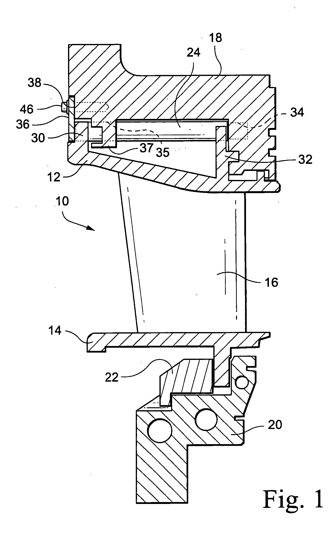
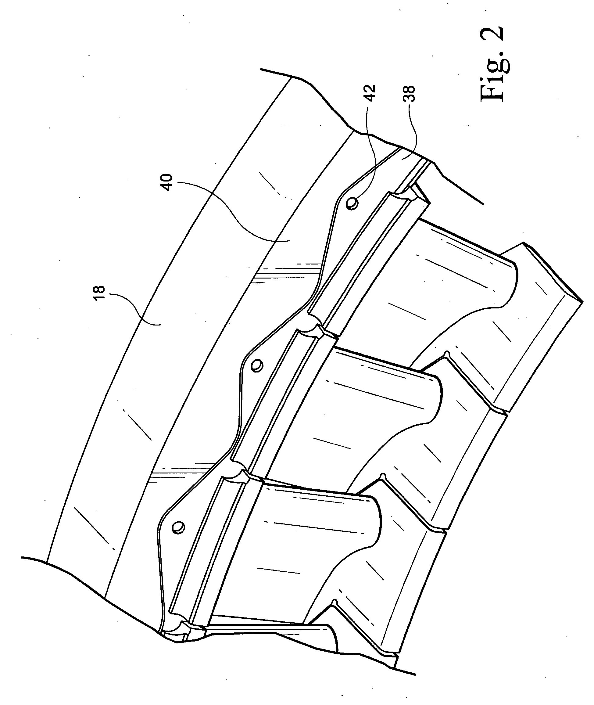
[0003] According to a preferred aspect of the present invention, the outer band of each nozzle segment is provided with an axially extending hole for receiving an anti-rotation pin which can be readily removed and replaced, enabling removal and replacement of selected nozzle segments in an axial direction and without the need to remove the case. Each axially extending anti-rotation pin extends through radially outwardly extending slots in radial outward flanges of the outer band of the corresponding nozzle segment and through corresponding holes in the retainer ring. Retainer plate segments overlie the end axial faces of the anti-rotation pins and are secured to the retainer ring. By removing the retention plate segments, the anti-rotation pins can be removed in an axial forward direction, enabling circumferential removal and insertion of each of the nozzle segments.

Problems solved by technology

These radially oriented prior anti-rotation pins encounter space limitations which prevent removal of certain of the pins when performing turbine maintenance in situ.
For example, at the horizontal joint, the case is very close to the retention ring and the anti-rotation pin cannot be removed, leaving the nozzle segments essentially non-removable.
As a consequence, maintenance and testing operations have been found to be laborious and costly.

Method used


Image

  • Apparatus and methods for removing and installing a selected nozzle segment of a gas turbine in an axial direction
  • Apparatus and methods for removing and installing a selected nozzle segment of a gas turbine in an axial direction
  • Apparatus and methods for removing and installing a selected nozzle segment of a gas turbine in an axial direction

Examples


Embodiment Construction

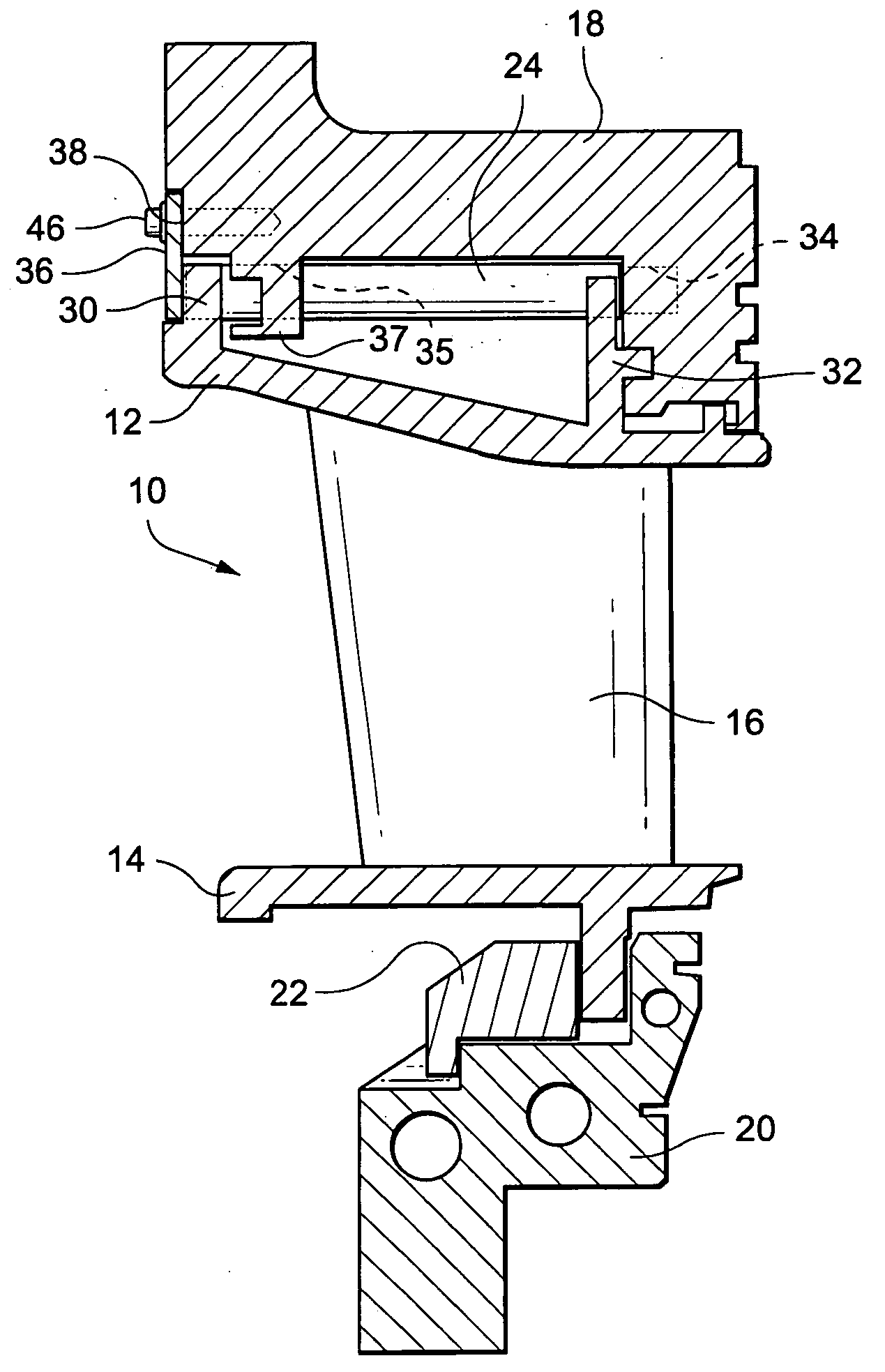
[0015] Referring to FIG. 1, there is illustrated a nozzle segment, generally designated 10, and including an outer band 12, an inner band 14 and one or more nozzle vanes 16 extending between the outer and inner bands. The outer bands 12 of the nozzle segments 10 are secured to an outer retention ring 18. The inner bands 14 are secured to an inner casing 20, by an annular array of inner diameter retention plates 22. The retention plates 22 are bolted to the casing 20 with bolts, not shown, extending in an axial direction, enabling removal of the inner diameter retention plates 22 in an axial forward direction.

[0016] In accordance with a preferred aspect of the present invention, axially extending anti-rotation pins 24 are provided between the outer bands 12 and the outer retention ring 18, preferably one pin 24 per segment 10. Particularly, the outer band 12 includes a pair of radially outwardly extending flanges 30 and 32, respectively, axially spaced one from the other. Axially al...


PUM


Abstract

Nozzle segments are secured to a retention ring against circumferential rotation by anti-rotation pins extending generally axially between the outer bands of the nozzle segments and the retention ring. Retention plate segments overlie the ends of the pins, preventing axial removal thereof. To remove a selected nozzle segment, inner diameter retention plate segments and selected retention plate segments are removed, the latter exposing the ends of the pins for axial withdrawal. Upon removal of a predetermined number of pins, the nozzle segments adjacent the selected segment are displaced away from the latter segment to open a gap between the selected segment and adjacent segments whereby the selected segment can be removed in an axial direction.

Description

BACKGROUND OF THE INVENTION [0001] The present invention relates to apparatus and methods for removing and installing a selected nozzle segment relative to a nozzle retention ring of a gas turbine and particularly relates to axially oriented anti-rotation pins for preventing circumferential movement of the nozzle segments and enabling removal and insertion of the anti-rotation pins in an axial direction to facilitate removal and installation of a selected nozzle segment without removal of the casing. [0002] In gas turbines, the nozzle stages are typically formed by an annular array of nozzle segments spaced circumferentially one from the other about the axis of the turbine. For example, in the first stage of the turbine, the nozzle segments, each including outer and inner bands with one or more nozzle vanes extending therebetween, are secured to annular outer and inner retention rings, respectively. In prior gas turbines, anti-rotation pins typically extend radially between the oute...

Claims


Application Information

Patent Timeline
IPC IPC(8): F01D9/04F01D25/24
CPCF01D9/042F05D2230/80F05D2230/64F01D25/246
Inventor ARNESS, BRIAN PETERGREENE, JOHN ELLINGTONFARRAL, LINDA JEANCHAN, SZE BUN BRIAN
Owner GENERAL ELECTRIC CO
Learn More