

Junction socket
a junction socket and socket technology, applied in the direction of coupling contact members, coupling device connections, multiple conductor connectors, etc., can solve the problems of reducing contact stability, increasing the cost of electronic components, and unable to solve the problem perfectly, so as to improve the contact stability of the male terminal and prevent deformation
- Summary
- Abstract
- Description
- Claims
- Application Information
AI Technical Summary
Benefits of technology
Problems solved by technology
Method used
Image

Examples
first embodiment
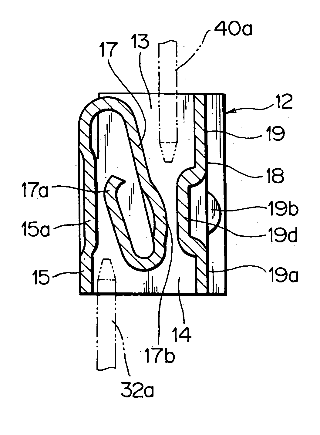
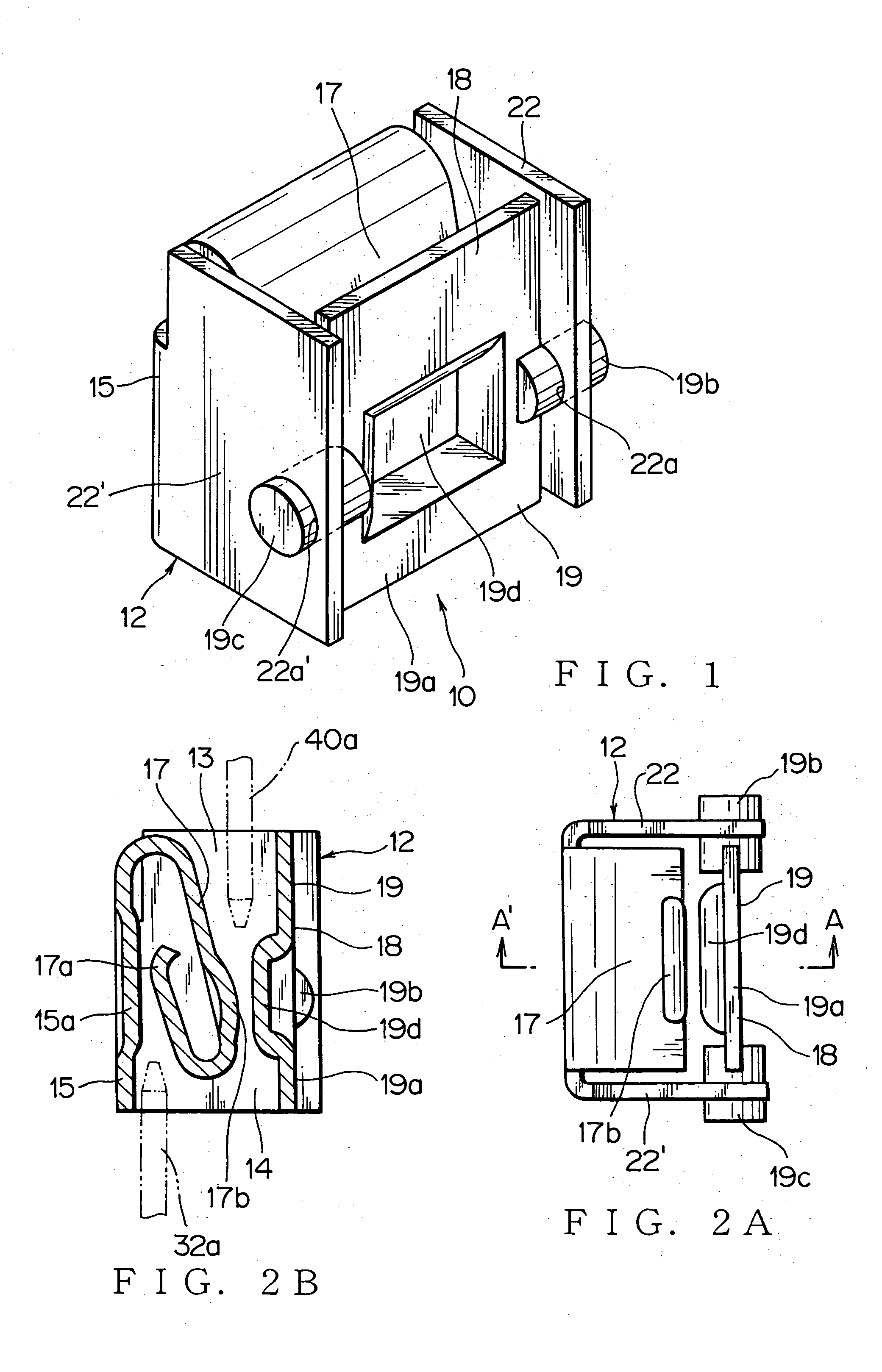
[0059] The junction socket 10 of this first embodiment prevents a resilient contact piece 17 from being pried to be damaged by the male terminals 32a, 40a being inserted into the junction socket 10. Further, this junction socket 10 guarantees stable contact pressure between the terminals, and thereby improves contact stability between the terminals.
[0060] This junction socket 10 has a receptacle 12 to receive upper and lower male terminals 40a, 32a in directions opposite to each other and to electrically connect them to each other. This junction socket includes a front wall 15; a rear wall 18; sidewalls 22, 22′ at both sides of the front and rear walls 15, 18; top and bottom openings 13, 14 formed respectively at both ends of the front and rear walls 15, 18; and the resilient contact piece 17 extended from the front wall 15, and bent twice inwardly in vicinities of the top and bottom openings 13, 14 of the receptacle 12. The rear wall 18 is configured with a movable contact piece 19...
second embodiment
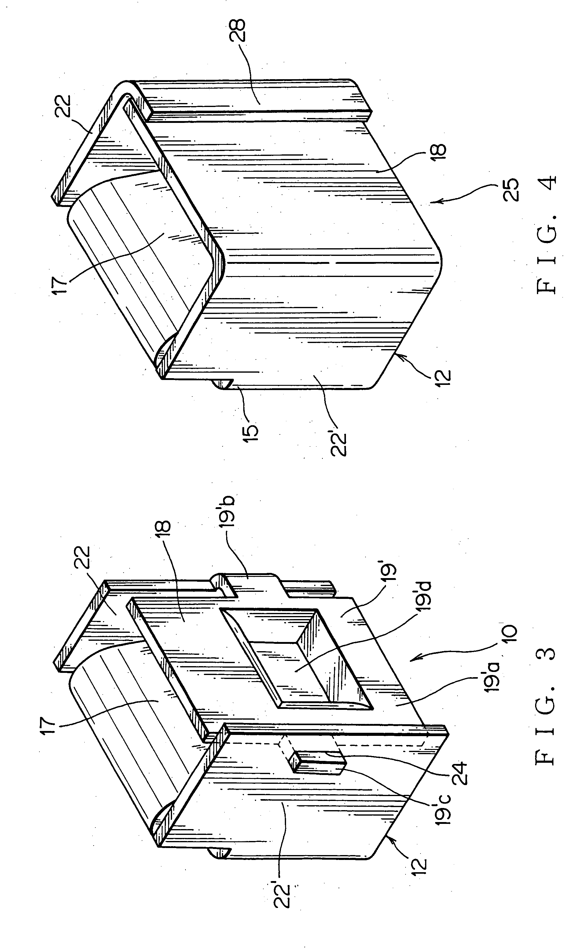
[0068] The junction socket 25 can compensate for angle errors of the two male terminals 32a, 40a, being inserted thereinto in directions opposite to each other, with a simple configuration. A resilient contact piece 17 is extended from a front wall 15, and bent twice inwardly in vicinities of an top and bottom openings 13, 14 of the receptacle 12. A first contact projection 26 facing to the resilient contact piece 17 is provided on the front wall 15. A second contact projection 27 facing to the resilient contact piece 17 is provided on the rear wall 18. When being inserted downward into the top opening 13 from a base of the resilient contact piece 17, the upper male terminal 40a is held between the resilient contact piece 17 and the second contact projection 27 on the rear wall 18. When being inserted upward into the bottom opening 14, the lower male terminal 32a is held between the resilient contact piece 17 and the first contact projection 26 on the front wall 15. Further, in this...
PUM
 Abstract
Description
Claims
Application Information