Reception apparatus

Inactive Publication Date: 2005-05-26
SHARP KK
View PDF10 Cites 34 Cited by
  • Summary
  • Abstract
  • Description
  • Claims
  • Application Information

AI Technical Summary

Benefits of technology

[0012] According to the present invention, it is possible to receive a plurality of channels and to receive the channel to be displayed on the main screen always via the antenna that yields the best reception condition. This makes it possible to display stable pictures on the main screen. Moreover, it is possible to stop the supply of electric power to the tuners that are not performing reception operation and thereby to

Problems solved by technology

When reception condition is poor, it is not possible to reproduce pictures and sounds properly.
With this configuration, it is indeed possible to select and output the broadcast signal receiv

Method used


Image

  • Reception apparatus
  • Reception apparatus
  • Reception apparatus

Examples


Example

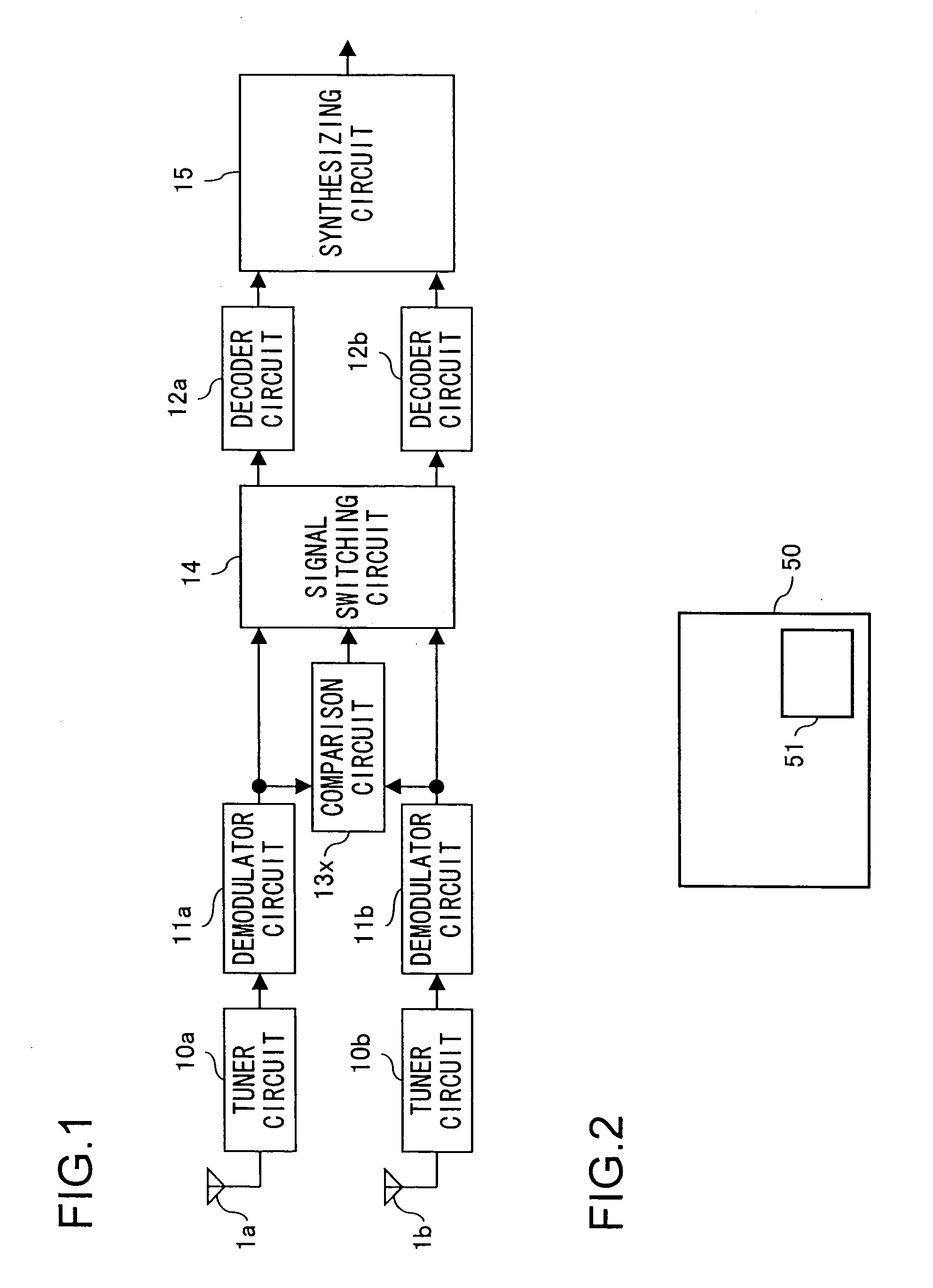
[0022] A first embodiment of the invention will be described below with reference to the drawings. FIG. 1 is a block diagram showing the internal configuration of the reception apparatus of this embodiment. In the reception apparatus shown in FIG. 1, such components as are found also in FIG. 9 are identified with common reference numerals.

[0023] The reception apparatus shown in FIG. 1 is provided with: antennas 1a and 1b; tuner circuits 10a and 10b; demodulator circuits 11a and 11b; a comparison circuit 13x; a signal switching circuit 14 that switches between the signals from the demodulator circuits 11a and 11b; decoder circuits 12a and 12b that decode the signals fed from the signal switching circuit 14; and a synthesizing circuit 15 that synthesizes together the signals decoded by the decoder circuits 12a and 12b. Here, the tuner circuits 10a and 10b each include, like the tuner circuit 10 in FIG. 8, a BPF 2, an RF amplifier 3, a BPF 4, a mixer 5, a VCO 6, and a PLL 7.

[0024] Th...

Example

[0040] A second embodiment of the invention will be described below with reference to the drawings. FIG. 4 is a block diagram showing the internal configuration of the reception apparatus of this embodiment. In the reception apparatus shown in FIG. 4, such components as are found also in FIG. 1 are identified with common reference numerals.

[0041] The reception apparatus shown in FIG. 4 is provided with: antennas 1a to 1d; tuner circuits 10a to 10d that are connected to the antenna 1a to 1d, respectively; demodulator circuits 11a to 11d that receive signals from the tuner circuits 10a to 10d, respectively; a comparison circuit 13y that compares the S / N ratios and bit error rates of the signals from the demodulator circuits 11a to 11d; a signal switching circuit 14 that switches between the signals from the demodulator circuits 11a to 11d; decoder circuits 12a to 12d that decode the signals fed from the signal switching circuit 14; and a synthesizing circuit 15 that synthesizes toget...

Example

THIRD EMBODIMENT

[0068] A third embodiment of the invention will be described below with reference to the drawings. FIG. 7 is a block diagram showing the internal configuration of the reception apparatus of this embodiment. In the reception apparatus shown in FIG. 7, such components as are found also in FIGS. 1 and 4 are identified with common reference numerals.

[0069] The reception apparatus shown in FIG. 7 is provided with: antennas 1a to 1d; tuner circuits 10a to 10d; demodulator circuits 11a to 11d; a comparison circuit 13a that compares the S / N ratios and bit error rates of the signals from the demodulator circuits 11a and 11b; a comparison circuit 13b that compares the S / N ratios and bit error rates of the signals from the demodulator circuits 11c and 11d; a switch SW1 that selects one of the signals from the comparison circuit 13a and the demodulator circuits 11a and 11c; a switch SW2 that selects one of the signals from the comparison circuit 13b and the demodulator circuit...


PUM


Abstract

A comparison circuit 13x compares signals from demodulator circuits 11a and 11b and thereby compares the reception condition of the antennas 1a and 1b. The tuner circuit corresponding to the antenna that is yielding better reception condition selects the channel to be displayed on a main screen, and the tuner circuit corresponding to the other antenna selects the channel to be displayed on a sub screen.

Description

[0001] This nonprovisional application claims priority under 35 U.S.C. § 119(a) on Patent Application No. 2003-393668 filed in Japan on Nov. 25, 2003, the entire contents of which are hereby incorporated by reference. BACKGROUND OF THE INVENTION [0002] 1. Field of the Invention [0003] The present invention relates to a reception apparatus that adopts a diversity system involving a plurality of antennas, and more particularly to a reception apparatus for reproducing pictures. [0004] 2. Description of Related Art [0005] A conventional reception apparatus is provided with a tuner circuit 10, which includes: a BPF (band-pass filter) 2 that selects from the radio-frequency signals received via an antenna 1 those within a desired frequency band; an RF amplifier 3 that amplifies the radio-frequency signals that have passed through the BPF 2; a BPF (band-pass filter) 4 that selects from the radio-frequency signals amplified by the RF amplifier 3 those within the desired frequency band; a mi...

Claims


Application Information

Patent Timeline
IPC IPC(8): H04B17/40H04B7/08H04N5/44H04N5/50
CPCH04B7/082H04N5/45H04N5/50H04N21/44209H04N21/4316H04N21/4383H04N21/4263
Inventor OIWA, KOJI
Owner SHARP KK
Why Eureka
Try Eureka