Reception apparatus
a technology of reception apparatus and antenna, which is applied in the field of reception apparatus, can solve the problems of not being able to properly reproduce pictures and sounds, and not being able to receive and reproduce broadcast signals of different channels at the same time, so as to optimize the reception condition of the antenna used, stable pictures on each screen, and reduce power consumption
- Summary
- Abstract
- Description
- Claims
- Application Information
AI Technical Summary
Benefits of technology
Problems solved by technology
Method used
Image
Examples
first embodiment
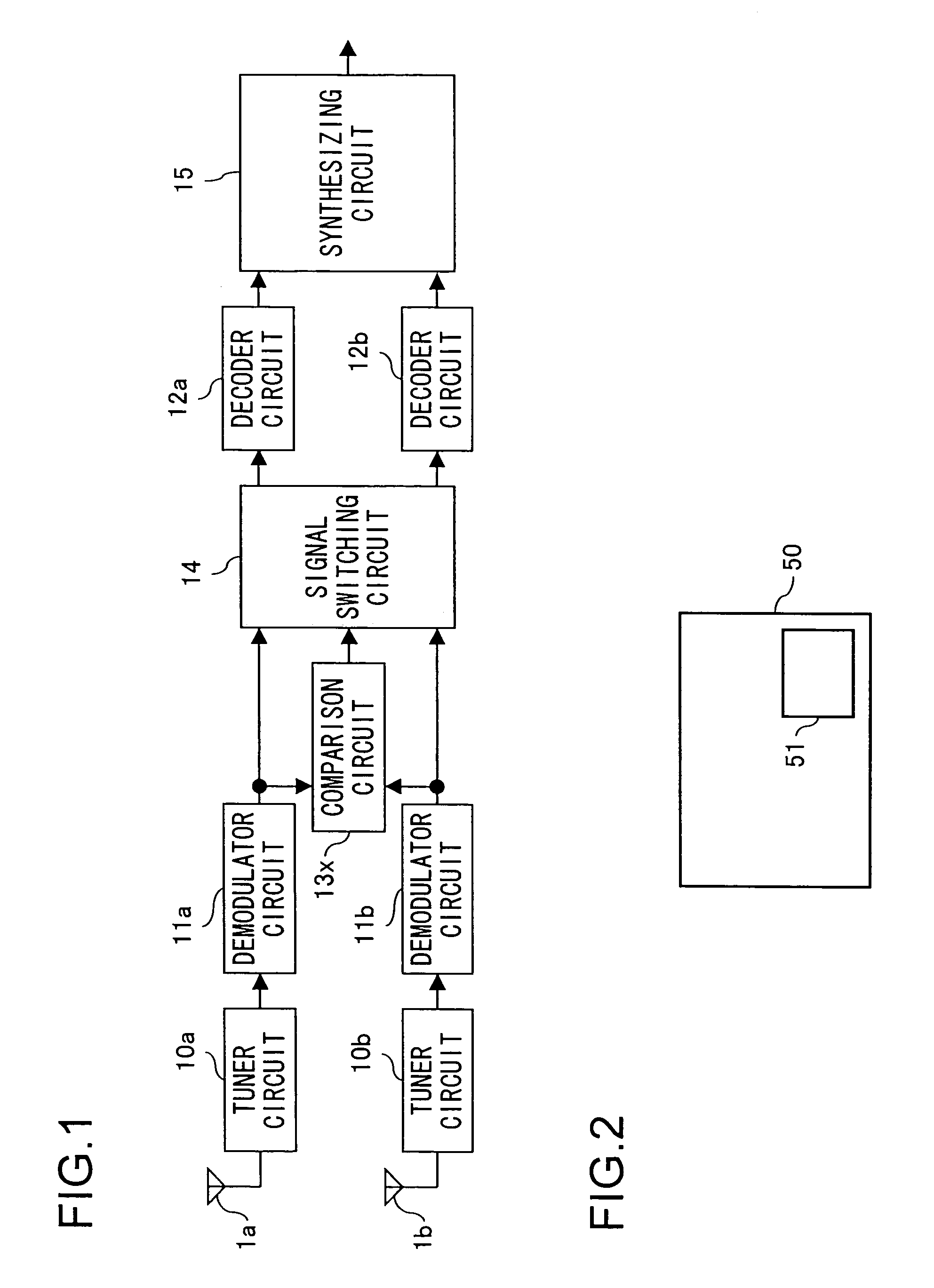
[0022]A first embodiment of the invention will be described below with reference to the drawings. FIG. 1 is a block diagram showing the internal configuration of the reception apparatus of this embodiment. In the reception apparatus shown in FIG. 1, such components as are found also in FIG. 9 are identified with common reference numerals.
[0023]The reception apparatus shown in FIG. 1 is provided with: antennas 1a and 1b; tuner circuits 10a and 10b; demodulator circuits 11a and 11b; a comparison circuit 13x; a signal switching circuit 14 that switches between the signals from the demodulator circuits 11a and 11b; decoder circuits 12a and 12b that decode the signals fed from the signal switching circuit 14; and a synthesizing circuit 15 that synthesizes together the signals decoded by the decoder circuits 12a and 12b. Here, the tuner circuits 10a and 10b each include, like the tuner circuit 10 in FIG. 8, a BPF 2, an RF amplifier 3, a BPF 4, a mixer 5, a VCO 6, and a PLL 7.
[0024]The tun...
second embodiment
[0040]A second embodiment of the invention will be described below with reference to the drawings. FIG. 4 is a block diagram showing the internal configuration of the reception apparatus of this embodiment. In the reception apparatus shown in FIG. 4, such components as are found also in FIG. 1 are identified with common reference numerals.
[0041]The reception apparatus shown in FIG. 4 is provided with: antennas 1a to 1d; tuner circuits 10a to 10d that are connected to the antenna 1a to 1d, respectively; demodulator circuits 11a to 11d that receive signals from the tuner circuits 10a to 10d, respectively; a comparison circuit 13y that compares the S / N ratios and bit error rates of the signals from the demodulator circuits 11a to 11d; a signal switching circuit 14 that switches between the signals from the demodulator circuits 11a to 11d; decoder circuits 12a to 12d that decode the signals fed from the signal switching circuit 14; and a synthesizing circuit 15 that synthesizes together...
third embodiment
[0068]A third embodiment of the invention will be described below with reference to the drawings. FIG. 7 is a block diagram showing the internal configuration of the reception apparatus of this embodiment. In the reception apparatus shown in FIG. 7, such components as are found also in FIGS. 1 and 4 are identified with common reference numerals.
[0069]The reception apparatus shown in FIG. 7 is provided with: antennas 1a to 1d; tuner circuits 10a to 10d; demodulator circuits 11a to 11d; a comparison circuit 13a that compares the S / N ratios and bit error rates of the signals from the demodulator circuits 11a and 11b; a comparison circuit 13b that compares the S / N ratios and bit error rates of the signals from the demodulator circuits 11c and 11d; a switch SW1 that selects one of the signals from the comparison circuit 13a and the demodulator circuits 11a and 11c; a switch SW2 that selects one of the signals from the comparison circuit 13b and the demodulator circuits 11b and 11d; a com...
PUM
 Abstract
Description
Claims
Application Information
 - R&D
- Intellectual Property
- Life Sciences
- Materials
- Tech Scout
- Unparalleled Data Quality
- Higher Quality Content
- 60% Fewer Hallucinations
Browse by: Latest US Patents, China's latest patents, Technical Efficacy Thesaurus, Application Domain, Technology Topic, Popular Technical Reports.
© 2025 PatSnap. All rights reserved.Legal|Privacy policy|Modern Slavery Act Transparency Statement|Sitemap|About US| Contact US: help@patsnap.com


