Cannulae having a redirecting tip

a technology of cannulae and tip, which is applied in the field of cannulae, can solve the problems of life-threatening complications, degrading the vasculature of patients requiring organ failure treatment, and increasing the severity of occlusion, so as to reduce the likelihood of harmful interaction

Inactive Publication Date: 2005-05-26
TC1 LLC
View PDF82 Cites 171 Cited by
  • Summary
  • Abstract
  • Description
  • Claims
  • Application Information

AI Technical Summary

Benefits of technology

[0008] Therefore, there is a need for a cannula that will lessen the likelihood of harmful interaction between the cannula, or fluid flowing out of the cannula, and the vessel in which the cannula resides, or through which the cannula is inserted.
[0009] In one embodiment, a percutaneous cannula is provided for discharging blood within a patient's vasculature. The cannula comprises a main cannula portion and a tip portion. The main cannula portion comprises a blood flow lumen that extends therethrough. The tip portion extends from the main cannula portion to a distal end of the cannula. The tip portion is configured to direct blood flow in a direction generally counter to the direction of flow through the blood flow lumen. The cannula is configured to prevent blood flow exiting the distal end from immediately discharging against a wall of a vessel in the vasculature.
[0011] In another embodiment, a percutaneous cannula comprises a main cannula portion, a discharge opening, and a transition portion. The transition portion extends distally from the main cannula portion and has a lumen therethrough. The transition portion is configured to engage an adjacent wall of a blood vessel to space the discharge opening of the cannula from the adjacent wall of the blood vessel. Blood discharge from a blood flow lumen through the discharge opening that directly impacts upon the blood vessel wall is substantially reduced by this arrangement.

Problems solved by technology

The vasculature of patients requiring treatment of organ failure often is somewhat degraded.
As is known, such matter tends to occlude the vessel at least to some degree, and such occlusion can become more severe over time.
If the deposited matter is dislodged it can drift in the vasculature to another location, become lodged in a smaller vessel, and cause an embolism or other severe harm potentially leading to life-threatening complications.
Some organ failure treatments can inadvertently cause embolism and other related complications.

Method used


Image

  • Cannulae having a redirecting tip
  • Cannulae having a redirecting tip
  • Cannulae having a redirecting tip

Examples


Embodiment Construction

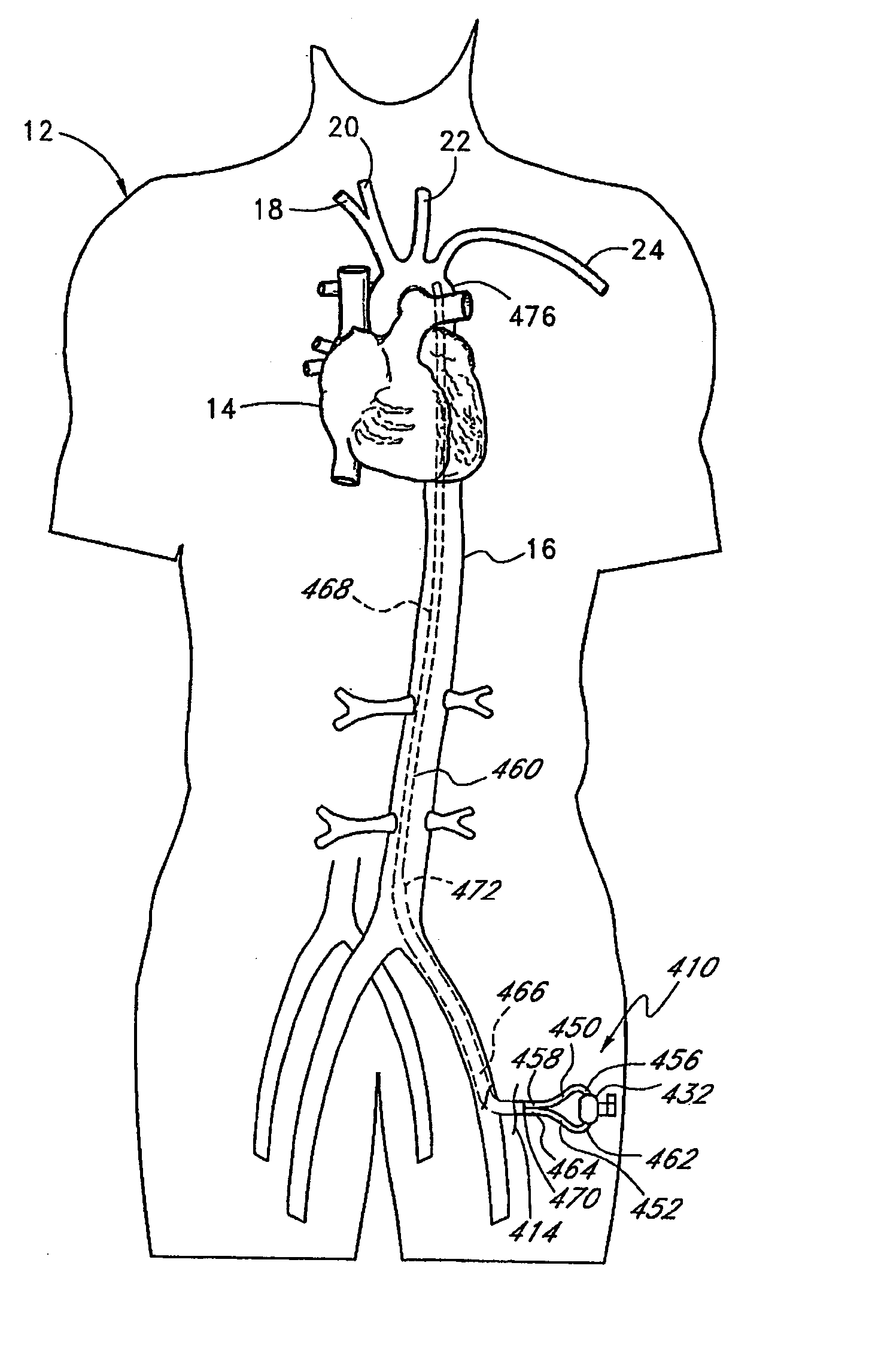
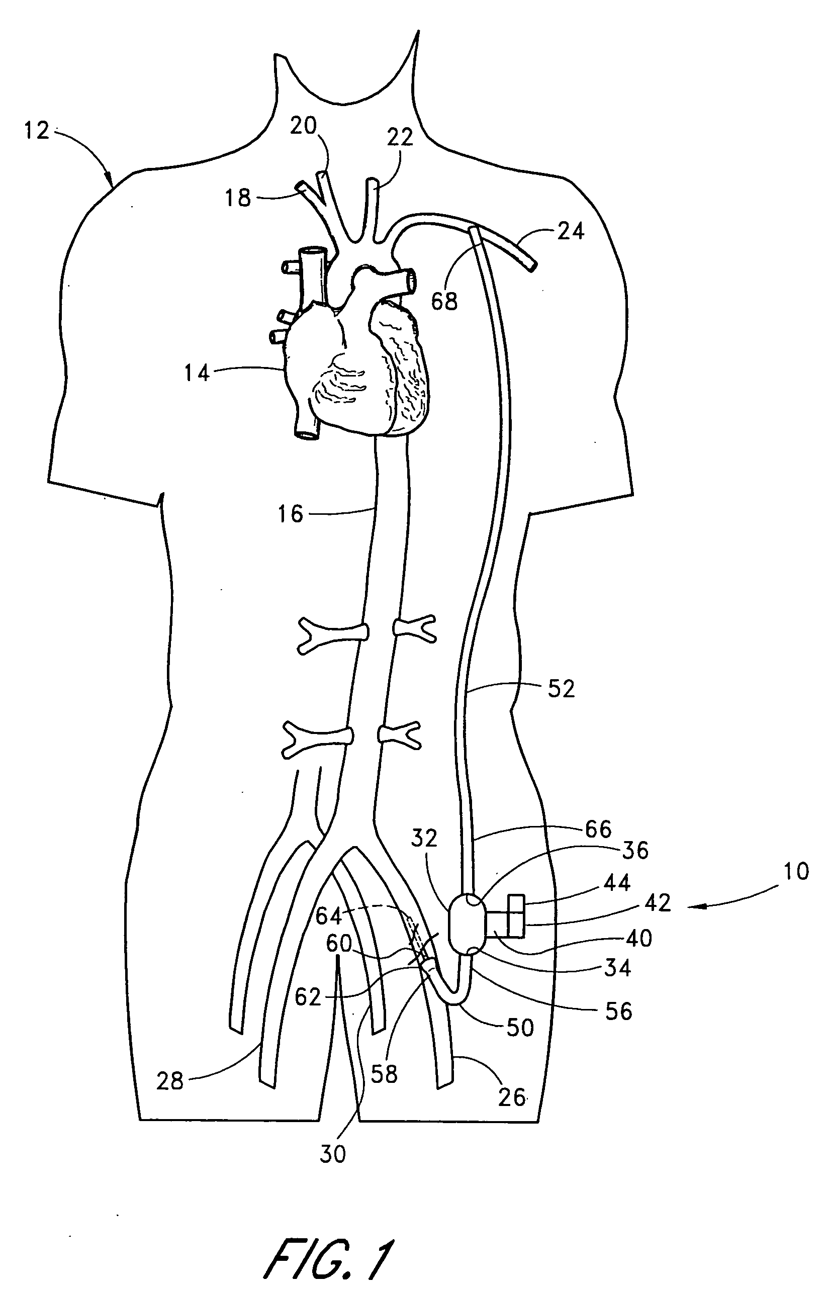
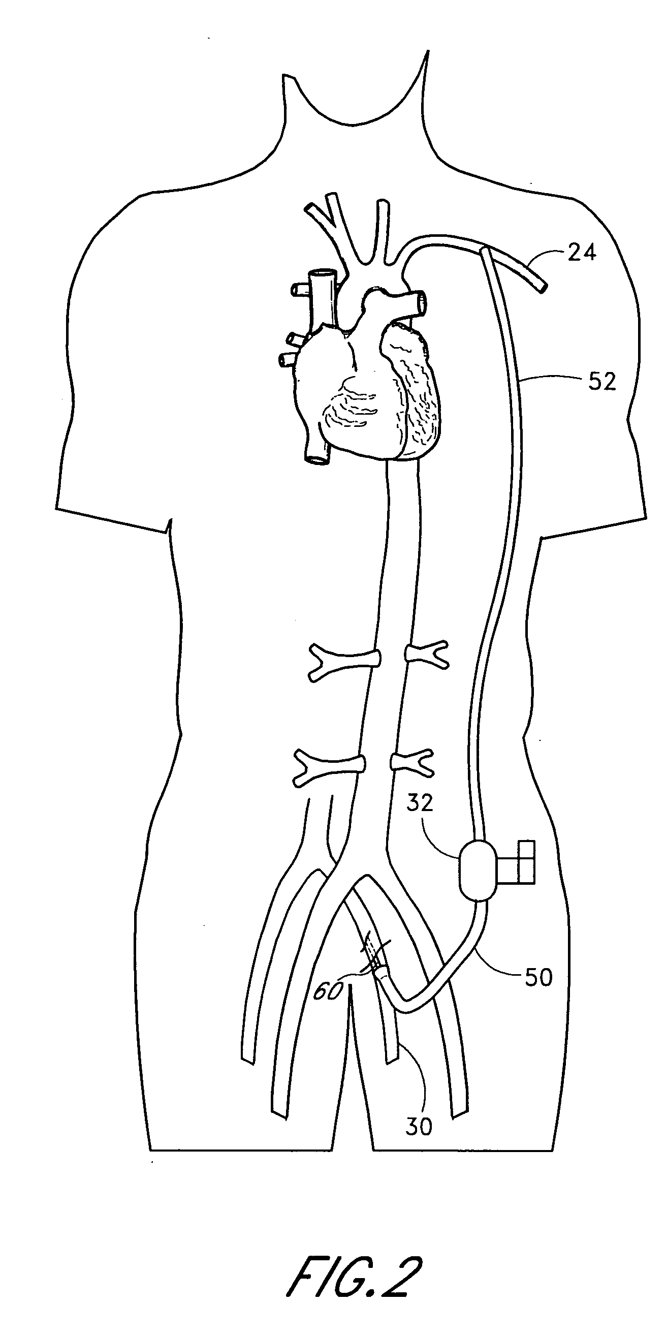
[0057] Turning now to the drawings provided herein, more detailed descriptions of various embodiments of heart assist systems and cannulae for use therewith are provided below.

[0058] I. Extracardiac Heart Assist Systems and Methods

[0059] A variety of cannulae are described herein that can be used in connection with a variety of heart assist systems that supplement blood perfusion. Such systems preferably are extracardiac in nature. In other words, the systems supplement blood perfusion, without the need to interface directly with the heart and aorta. Thus, the systems can be applied without major invasive surgery. The systems also lessen the hemodynamic burden or workload on the heart by reducing afterload, impedence, and / or left ventricular end diastolic pressure and volume (preload). The systems also advantageously increase peripheral organ perfusion and provide improvement in neurohormonal status. As discussed more fully below, the systems can be applied using one or more cannu...


PUM


Abstract

A percutaneous cannula is provided that directs blood into a vessel of a patient. The cannula includes a main cannula portion and a tip portion. The tip portion directs blood-flow in a direction generally counter to the direction of flow through the lumen. The cannula is configured to prevent blood-flow exiting the distal end from immediately discharging against a wall of the vessel.

Description

BACKGROUND OF THE INVENTION [0001] 1. Field of the Invention [0002] This application relates to cannulae and, in particular, to cannulae having a tip configured to redirect the flow of fluid out of the cannula. [0003] 2. Description of the Related Art [0004] Treatment and diagnosis of a variety of health conditions in a patient can involve withdrawing blood from the patient's vascular system. For example, a syringe can be inserted into the patient's vasculature to withdraw blood for testing. It is sometimes necessary to introduce blood or other fluids into a patient's vasculature, e.g., an injection via an intravenous line, to provide treatment or obtain a diagnosis. [0005] Treatment of organ failure can involve coordinated withdrawal and introduction of blood, in connection with some additional treatment. Dialysis, for example, involves withdrawing blood from the vasculature, filtering the blood, and infusing the blood back into the vasculature for further circulation. An emerging ...

Claims


Application Information

Patent Timeline
Patent Type & Authority Applications(United States)
IPC IPC(8): A61M1/10A61M1/12A61M1/36A61M5/142A61M25/00A61M39/10
CPCA61M1/101A61M1/125A61M1/3655A61M5/14244A61M25/001A61M25/003A61M25/0041A61M25/0068A61M25/007A61M25/0071A61M25/0074A61M25/0075A61M25/0082A61M25/04A61M2025/0031A61M2025/0037A61M2025/1047A61M1/1008A61M1/1034A61M1/122A61M1/3653A61M1/3659A61M60/414A61M60/894A61M60/148A61M60/232A61M60/237A61M60/152
Inventor BOLLING, STEVEN F.O'LEARY, SHAWNPECOR, ROBERTSHARP, BRADVIOLE, ANTHONYWERNER, WOLFGANG
Owner TC1 LLC
Why Eureka
Try Eureka