Methods and systems for angular-dependent backscatter spatial compounding

a technology of spatial compounding and backscatter, applied in the field of diagnostic ultrasound systems, can solve the problems of reducing the viewing capability of bodies of interest within these areas, removing valuable diagnostic information from the image,

Active Publication Date: 2005-05-26
GENERAL ELECTRIC CO
View PDF21 Cites 14 Cited by
  • Summary
  • Abstract
  • Description
  • Claims
  • Application Information

AI Technical Summary

Problems solved by technology

However, simply removing specular interference and distal end shadows from the image may also remove valuable diagnostic information from the image.
Although spatial compounding may improve image quality by reducing and specular reflections and distal end shadows, spatial compounding may also reduce the viewing capability of bodies of interest within these areas.

Method used


Image

  • Methods and systems for angular-dependent backscatter spatial compounding
  • Methods and systems for angular-dependent backscatter spatial compounding
  • Methods and systems for angular-dependent backscatter spatial compounding

Examples


Embodiment Construction

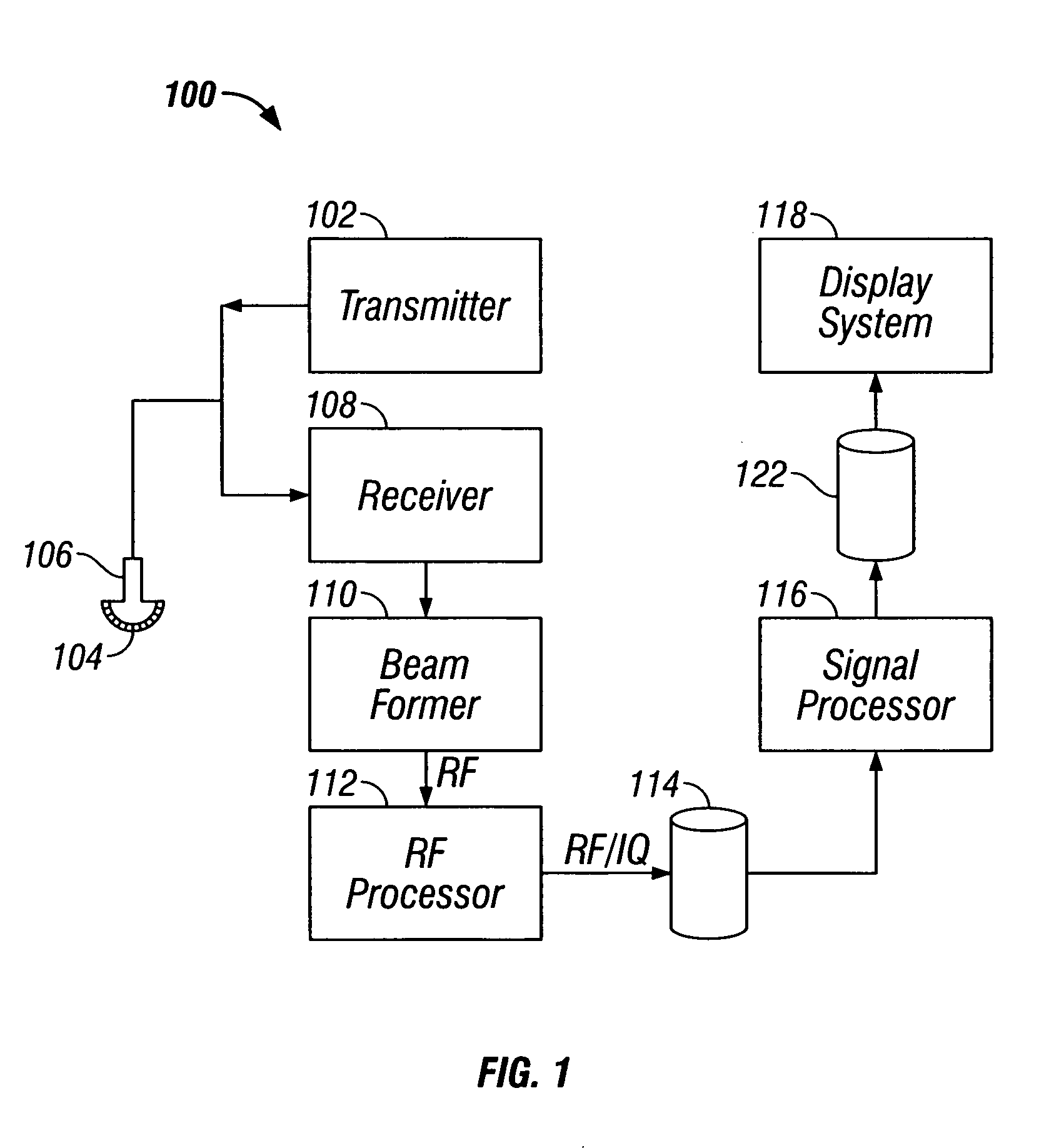
[0013]FIG. 1 is a block diagram of an exemplary ultrasound system 100. Ultrasound system 100 includes a transmitter 102 which drives a n array of elements 104 within a probe 106 to emit pulsed ultrasonic signals into a body. A variety of geometries may be used. The ultrasonic signals are back-scattered from density interfaces and / or structures in the body, like blood cells or muscular tissue, to produce echoes which return to elements 104. The echoes are received by a receiver 108. The received echoes are passed through a beamformer 110, which performs beamforming and outputs an RF signal. The RF signal then passes through an RF processor 112. Alternatively, RF processor 112 may include a complex demodulator (not shown) that demodulates the RF signal to form IQ data pairs representative of the echo signals. The RF or IQ signal data may then be routed directly to RF / IQ buffer 114 for temporary storage.

[0014] Ultrasound system 100 also includes a signal processor 116 to process the a...


PUM


Abstract

A method of medical ultrasonic imaging is provided. The method includes transmitting a plurality of ultrasonic waves into a volume such that each successive wave is transmitted into the volume at a steering angle different than each preceding transmitted wave, receiving a plurality of ultrasonic echoes for each of the plurality of transmitted ultrasonic waves, each received echo is indicative of a density interface within the volume, each set of received echoes that corresponds to a single transmitted wave defines a steering frame, combining steering frames into a compound image, and identifying distal shadows in each steering frame.

Description

BACKGROUND OF THE INVENTION [0001] The present invention relates to diagnostic ultrasound systems. In particular, the present invention relates to methods and apparatus for acquiring and processing ultrasound data to highlight artifacts in ultrasound images. [0002] At least some known ultrasonic systems are capable of spatially compounding a number of ultrasound images of a given target that have been obtained from a plurality of steering angles. The images are combined into a single compounded image by combining the data received from each point in the compound image target which has been received from each steering angle. Real time spatial compound imaging may be performed by acquiring a series of partially overlapping component image frames from substantially independent steering angles. An array transducer may be utilized to implement electronic beam steering and / or electronic translation of the component frames. The component frames are combined into a compound image by summati...

Claims


Application Information

Patent Timeline
Patent Type & Authority Applications(United States)
IPC IPC(8): A61B8/00G01S7/52G01S15/89
CPCA61B8/00A61B8/5269G01S15/8995G01S7/52046
Inventor MILLER, STEVEN CHARLES
Owner GENERAL ELECTRIC CO
Why Eureka
Try Eureka