Systems and methods for automatically placing nodes in an ad hoc network

Active Publication Date: 2005-05-26
RAYTHEON BBN TECH CORP
View PDF55 Cites 55 Cited by
  • Summary
  • Abstract
  • Description
  • Claims
  • Application Information

AI Technical Summary

Benefits of technology

[0015] According to a further aspect, at least one node in a network that includes multiple nodes is provided. The node(s) may include a network device that is capable of moving within the network and a movement controller that is configured to generate a current view of the network. The movement controller is further configured to form blocks from groups of one or more of the nodes in the network based on the current view of the network and identify one or more of the blocks to move to make the network biconnected.
[0016] According to another aspect, a method for achieving biconnectivity in a network that includes multiple nodes is provided. The method may include generating a graph of the network and identifying cutvertices in the network. The method may further include moving one or more of the nodes in the network to systematically remove the cutvertices from the network and form a biconnected network.
[0017] According to yet another aspect, a method for achieving biconnectivity in a non-biconnected network that includes multiple nodes is provided. The method may include determining a geographic center of the non-biconnected network and moving each of one or more of the nodes a weighted distance towards the geographic center to transform the non-biconnected network to a biconnected network.
[0018] According to a further aspect, a system for achieving biconnectivity in a non-biconnected network that includes multiple nodes is provided. The system may include means for identifying a geographic center of the non

Problems solved by technology
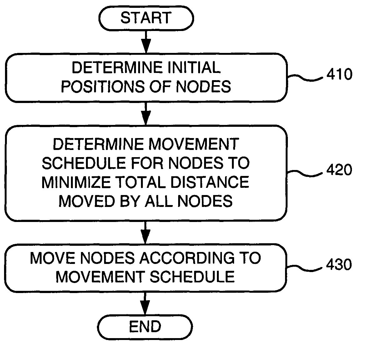
In most application scenarios, such as the ones described in the previous paragraph, it is difficult to guarantee the presence of a wireless base station that can coordinate the flow of information between any two robot units.
Moreover, the movement of robots can be severely restricted in order to keep in communication range of the

Method used


Image

  • Systems and methods for automatically placing nodes in an ad hoc network
  • Systems and methods for automatically placing nodes in an ad hoc network
  • Systems and methods for automatically placing nodes in an ad hoc network

Examples


Embodiment Construction

[0038] The following detailed description of the invention refers to the accompanying drawings. The same reference numbers in different drawings may identify the same or similar elements. Also, the following detailed description does not limit the invention. Instead, the scope of the invention is defined by the appended claims and equivalents.

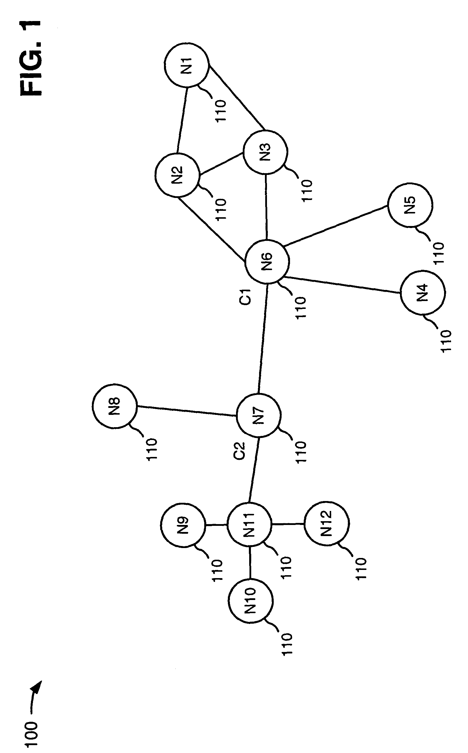
[0039] Autonomous and semi-autonomous mobile multi-robot systems require a wireless communication network in order to communicate with each other and collaboratively accomplish a given task. A multihop communications network that is self-forming, self-healing and self-organizing is well suited for such mobile robotic systems that exist in unpredictable and constantly changing environments. Because every node in a multihop (or ad hoc) network is responsible for forwarding packets to other nodes, however, the failure of a critical node can result in a network partition. Hence, it may be beneficial to have an ad hoc network configuration that can...


PUM


Abstract

A system may place nodes (110) within a non-biconnected network (100) that includes multiple interconnected nodes (110) to achieve biconnectivity within the network (100) and transform the network (100) from a non-biconnected one to a biconnected one. A non-biconnected network is one that necessarily becomes partitioned into two or more disconnected networks if a node in a critical position (termed a “cutvertex” node) should fail or otherwise become unavailable. A biconnected network is one that includes at least one additional network link (sometimes termed an “edge”) between nodes belonging to each of the otherwise potentially disconnected networks for the purpose of maintaining network communication therebetween if and when the cutvertex node fails or otherwise becomes unavailable. To achieve biconnectivity, the system may identify one or more nodes (110) to move and determine the direction and distance to move the one or more nodes (110). The system may then move the one or more nodes (110) in the determined direction and distance to transform the non-biconnected network (100) to a biconnected one.

Description

GOVERNMENT CONTRACT [0001] The U.S. Government may have a paid-up license in this invention and the right in limited circumstances to require the patent owner to license others on reasonable terms as provided for by the terms of Contract No. DASG60-02-C-0060 awarded by the Defense Advanced Research Projects Agency (DARPA).BACKGROUND OF THE INVENTION [0002] 1. Field of the Invention [0003] The present invention relates generally to wireless networks and, more particularly, to systems and methods for automatically placing or moving nodes in a wireless network to provide biconnectivity. [0004] 2. Description of Related Art [0005] Advances in electronics and mechanics have provided the basic technologies required for sophisticated robots. It is well recognized that robots have significant operational advantages over humans because they can perform tasks without requirements for rest, food, shelter, or task heterogeneity. This makes them potentially useful in future military exercises on...

Claims


Application Information

Patent Timeline
IPC IPC(8): H04L12/56
CPCG01S5/0289H04W4/08H04W84/18H04W64/00H04W28/04
Inventor BASU, PRITHWISHREDI, JASON KEITH
Owner RAYTHEON BBN TECH CORP
Why Eureka
Try Eureka