Power working machine

a working machine and working handle technology, applied in the field of power working machines, can solve the problems of cumbersome and complicated operation of the operating handle rotating and locking operation of the human operator b>202/b>, and achieve the effect of increasing operational ease and preventing the human operator from accidentally touching

Active Publication Date: 2005-06-02
HONDA MOTOR CO LTD
View PDF2 Cites 11 Cited by
  • Summary
  • Abstract
  • Description
  • Claims
  • Application Information

AI Technical Summary

Benefits of technology

[0016] Because the operating handle is generally in a closed loop shape, such as a rectangular loop or letter “O” shape, the human operator can, for example, shift his or her hand, gripping the throttle lever, over to the operation lever without temporarily unhanding the operating handle. As a result, the operating handle can be rotated by the human operator with increased ease.
[0017] Further, because the operation lever, which locks the throttle lever in the non-operating position simultaneously with unlocking of the lock mechanism, is located in a rear portion of the handle, the human operator is allowed to both unlock the lock mechanism and rotate the operating handle through a series of action, by just gripping the rear portion of the handle. Furthermore, because the throttle lever is located on a front portion of the handle remotely from the operation lever, it is possible to reliably prevent the human operator from accidentally touching the operation lever when operating the throttle lever. As a result, the operating handle can be rotated by the human operator with increased operational ease, and thus an “erroneous-operation preventing function” of the working machine can be significantly enhanced.

Problems solved by technology

However, with the power working machine 200, the human operator's rotating and locking operation of the operating handle 202 is very cumbersome and complicated because the human operator has to first rotate the handle 202 through a desired rotational angle relative to the machine body 201, disengage the throttle lock lever 204 from the throttle lever 203 and then grip the throttle lever 203 to thereby press the lock member 205 against the machine body 201 so as to lock the handle 202.
However, because, in the power working machine 300, the operation lever 305 is located only within a finger length from the throttle lever 303, the human operator might accidentally touch and thus erroneously operate the operation lever 305.

Method used


Image

  • Power working machine
  • Power working machine
  • Power working machine

Examples


Embodiment Construction

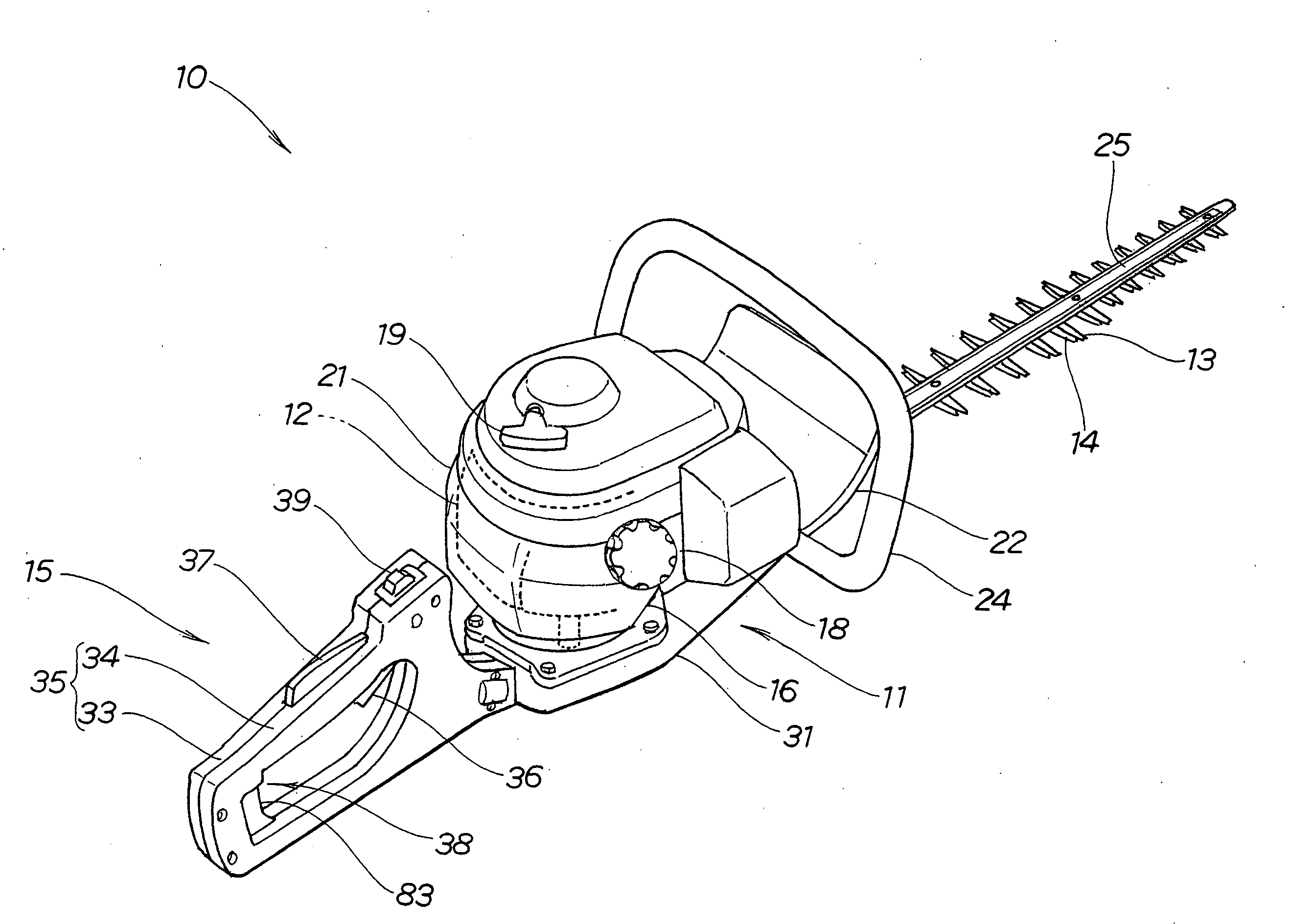
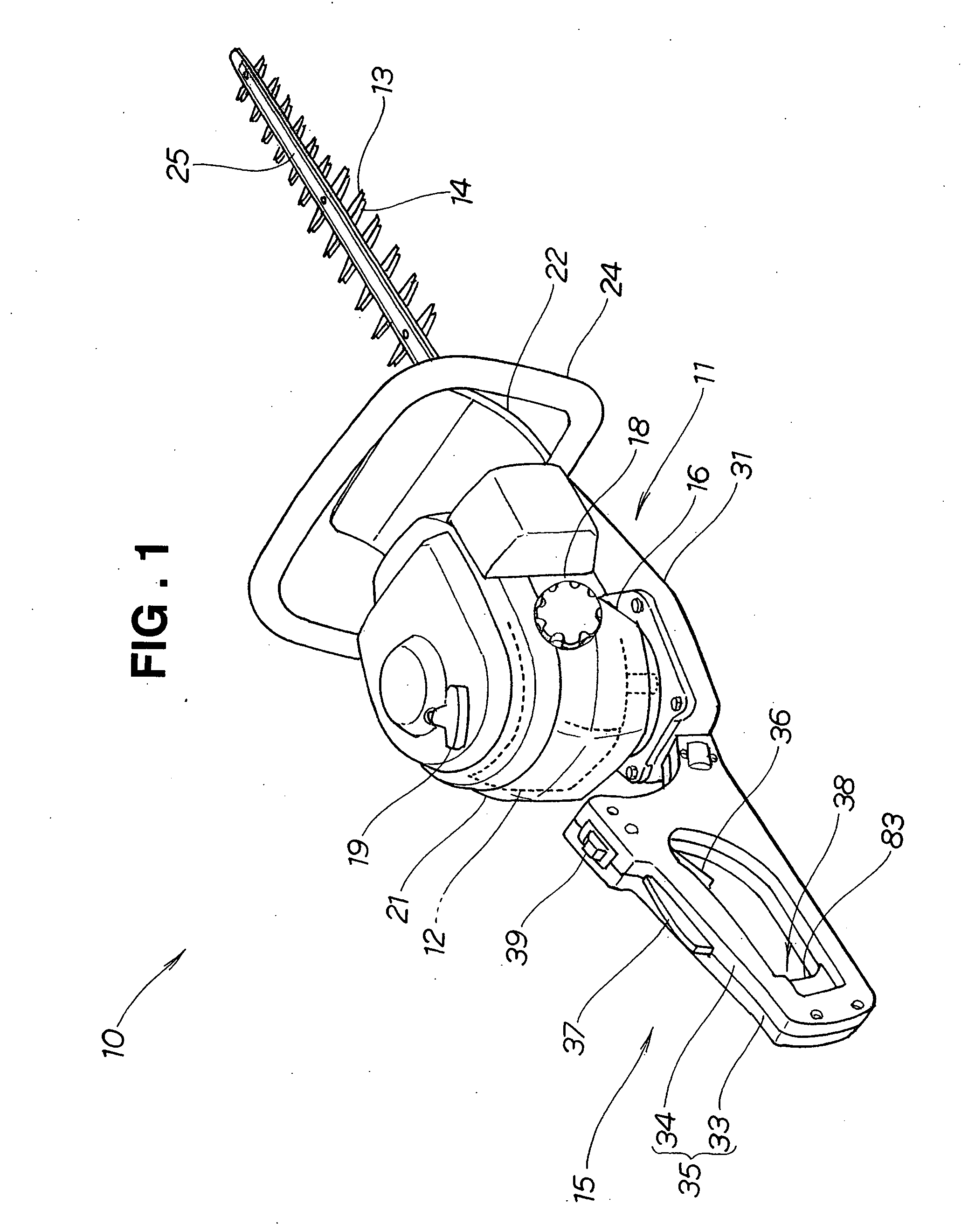
[0038]FIG. 1 is a perspective view of a power working machine in accordance with an embodiment of the present invention. The power working machine 10 of FIG. 1 is constructed as a “hedge trimmer”, where a rotation force output from a drive source 12, such as an engine, is converted, after appropriate speed reduction, into reciprocating movement and the reciprocating movement is delivered to upper and lower trimming blades 13 and 14 to trim a hedge. Also, in the power working machine 10, a rotatable operating handle 15 can be turned or rotated relative to the machine body in accordance with an operating posture or position of a human operator (user) when trimming an upper or side surface of a hedge.

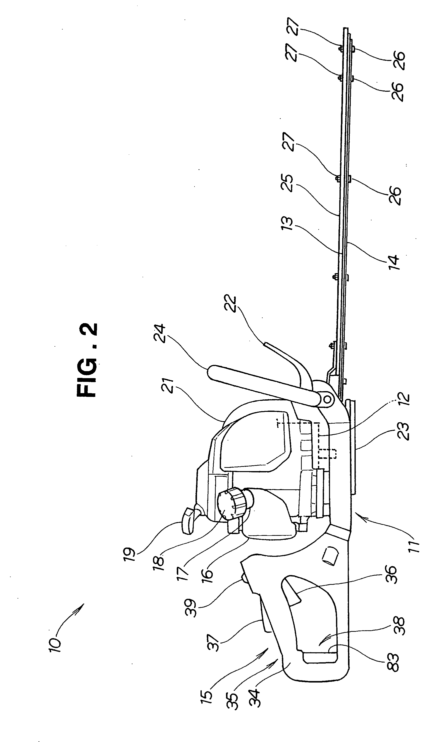
[0039]FIG. 2 is a side view of the power working machine 10. As shown, the power working machine (hedge trimmer) 10 includes the drive source 12 mounted generally centrally on a machine body 11, a fuel tank 16 for holding fuel to be supplied to the drive source 12, and a cap 18 covering a...


PUM

PropertyMeasurementUnit
shapeaaaaaaaaaa
rotational movementaaaaaaaaaa
workabilityaaaaaaaaaa

Abstract

In a power working machine where output power of a drive source is adjustable by a throttle lever pivotally movable between a non-operating position and an operating position, an operating handle, generally in the shape of a closed loop, is rotatably mounted on a shaft section extending from a machine body. Throttle lock lever is provided on the operating handle for disabling the pivotal movement of the throttle lever when necessary. The operating handle includes a lock mechanism for locking the handle at a desired rotational position, and an operation lever for unlocking the lock mechanism to permit rotational movement of the handle and simultaneously locking the throttle lock lever. Simultaneously with the unlocking of the lock mechanism, the operation lever locks the throttle lever in the non-operating position.

Description

FIELD OF THE INVENTION [0001] The present invention relates to a power working machine which can trim an upper surface, side surface, etc. of a hedge with an enhanced workability by allowing a human operator to rotate its operating handle in accordance with desired trimming positions. BACKGROUND OF THE INVENTION [0002] Examples of power working machines in practical use today include those in which an operating handle is rotatably mounted on a machine body, a throttle lever is mounted on the operating handle for adjustment of an output from a drive source, such as an engine, and a throttle lock lever is also mounted on the operating handle for locking the throttle lever. For practical use, it is only necessary that the power working machines include, in addition to the throttle lever and throttle lock lever, a lock mechanism provided on the machine body for locking the operating handle at a desired rotational angle relative to the machine body and an operation lever (lock-canceling ...

Claims


Application Information

Patent Timeline
Patent Type & Authority Applications(United States)
IPC IPC(8): B25F5/02A01G3/053A01G3/06B27B19/09
CPCA01G3/053Y10T16/44Y10T16/4713B25F5/02A01G3/06B27B19/09
Inventor SASAKI, HIDESHIHIRATSUNA, KENJIROUCHITANI, HIROAKI
Owner HONDA MOTOR CO LTD
Why Eureka
Try Eureka