Dispensing system for returnable bulk containers

a technology for shipping containers and dispensing systems, which is applied in the direction of opening closed containers, domestic articles, liquid/fluent solid measurements, etc., can solve the problems of not allowing direct flow control of materials, dust or residue generated by bulk material movement, and devices adding to the complexity and cost of containers, so as to achieve volume efficiency and cost. the effect of more cos

Inactive Publication Date: 2005-06-02
SERTAPAK PACKAGING
View PDF3 Cites 30 Cited by
  • Summary
  • Abstract
  • Description
  • Claims
  • Application Information

AI Technical Summary

Benefits of technology

[0013] A funnel cap is provided which is configured to replace the cover of the container, thereby retaining any structural integrity afforded by the cover. The funnel cap includes a selectively operable valve. The funnel cap operates in conjunction with a platen which is used to initially support the container in its upright position. The funnel cap and platen are movable away from one another to enable containers to be inserted or removed therefrom. The funnel cap and platen are movable toward one another to enable a container to be engaged and retained therein. The funnel cap and platen exert sufficient force on the container such that during lift and rotation of the container, it will not fall out. Once inverted, the contents of the container will have been gravitationally fed into the funnel. The valve in the funnel may then be selectively operated to dispense discreet quantities of flowable material. In general, by providing the dispensing mechanism in association with the emptying apparatus, the containers can be made more cost and volume efficient.
[0023] exerting a predetermined pressure on the container by said platen and funnel cap which will be sufficient to prevent the container from falling out from between said platen and funnel cap when rotated;

Problems solved by technology

Presently, containers are emptied by corner or side tear-away cutting, manual dump (of smaller boxes) or are side dumped, which methods do not permit direct flow control of the material.
Furthermore, these methods permit the materials to be exposed to the environment during dumping and may result in dust or residue being generated from the movement of the bulk material.
Some bulk containers include a hopper mechanism or a built-in dispensing port / valve but such devices add to the complexity and cost of the container and can be inconvenient or space-consuming for knock-down or disassemblable returnable containers.
However, because of the foldable nature of the sidewalls, these containers can be difficult to empty since once the top is removed, lateral forces on the walls can cause them to fold readily out of shape, making emptying by tipping or inversion problematic.

Method used


Image

  • Dispensing system for returnable bulk containers
  • Dispensing system for returnable bulk containers
  • Dispensing system for returnable bulk containers

Examples


Embodiment Construction

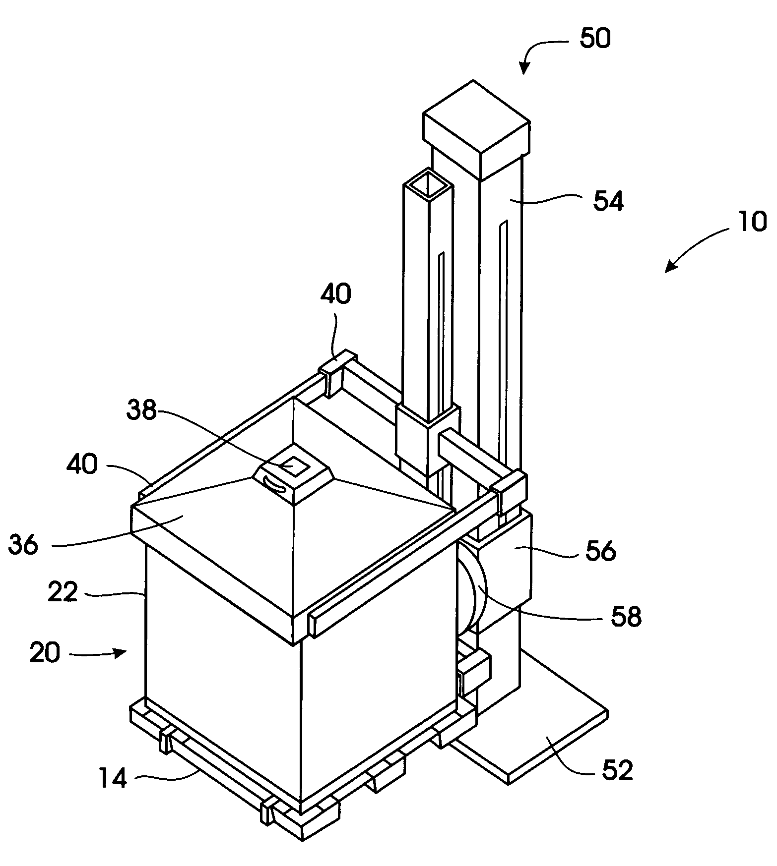
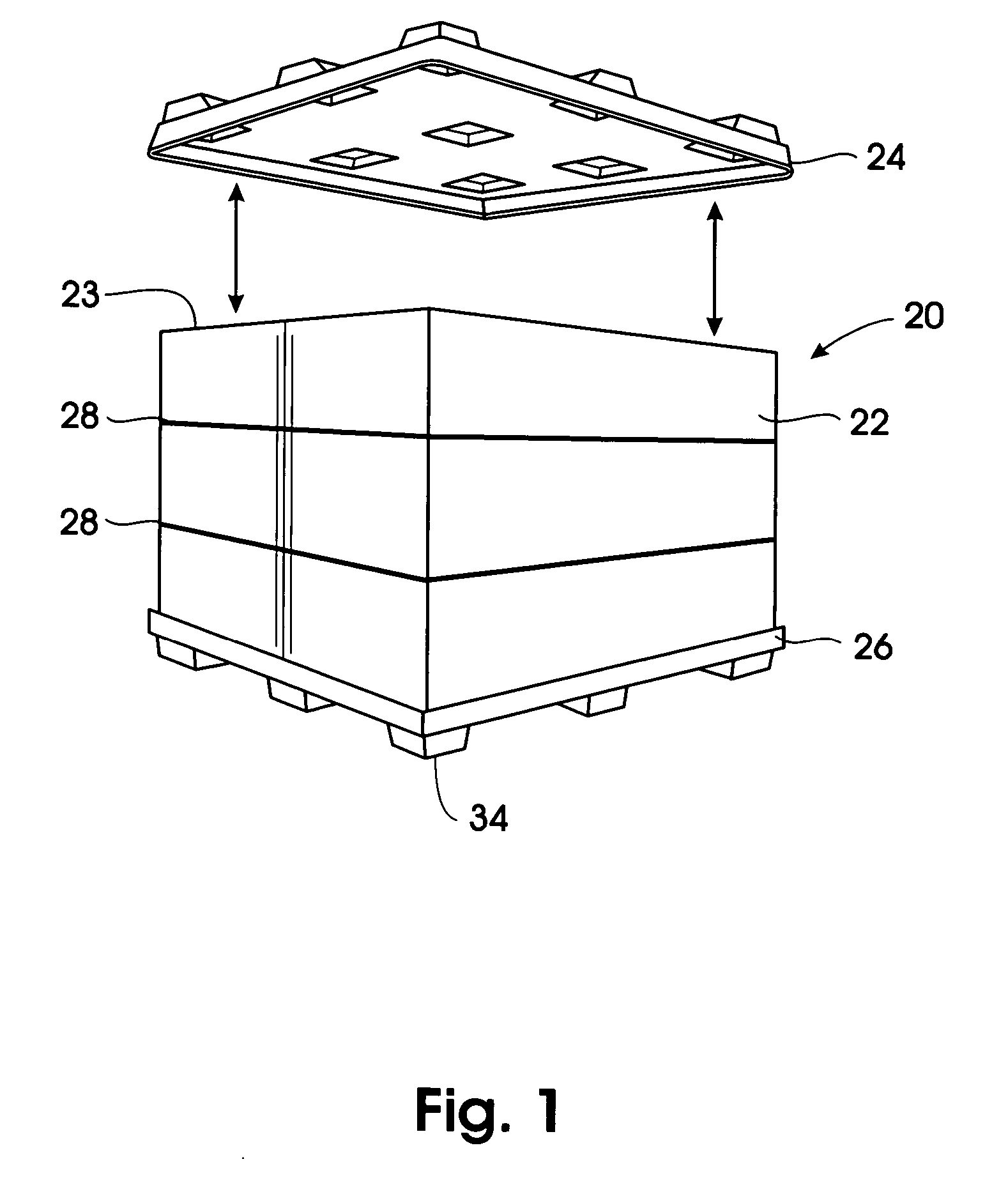
[0039] Referring to FIG. 1, the exemplary container / pack 20 in this case consists of a one-piece, tube-shaped, foldable sleeve 22 adapted to be positioned within a pair of thermoformed pallets 24,26 which form the top and bottom, respectively, of the container 20. The container may be double-banded with bands 28 for added strength during handling and transit. Typically, such containers have a footprint of 39×48″; 45×48″; or 48×48″ OD, a sleeve height of 45″ and, when loaded, can weigh upwards of 500 lbs.

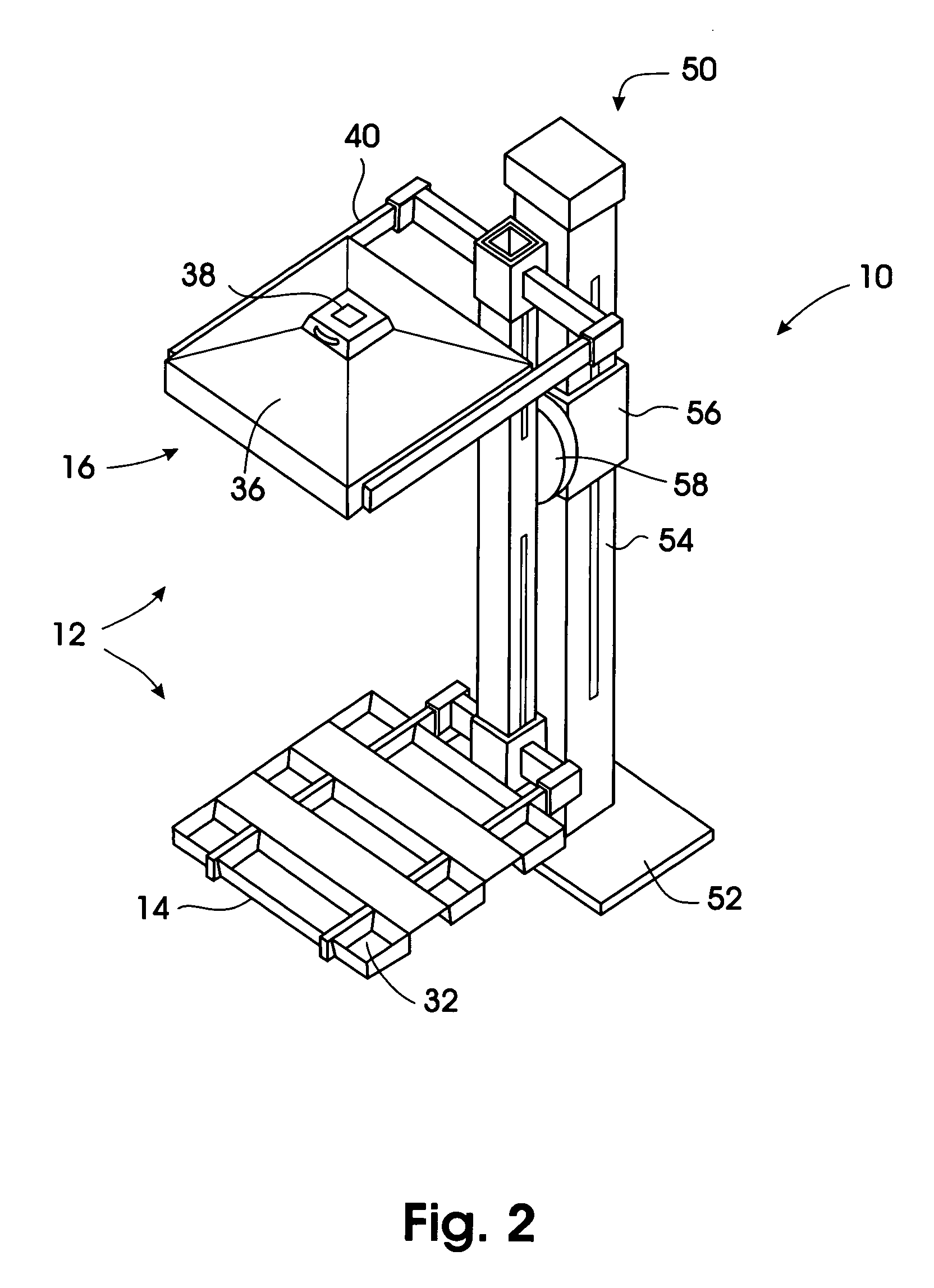
[0040] The dispensing system 10 is shown in FIG. 2. At the heart of the dispensing system 10 is the container press 12 which comprises a lower platen 14 and an upper hopper cap 16 movable relative toward and away from one another. While the lower platen 14 may be flat, it is preferably configured to accept and accommodate (stack with) the entire range of incoming pallet configurations. For example, the platen 14 shown in FIG. 2 is provided with wells 32 which accommodate feet 34 of ...


PUM


Abstract

A dispensing system for returnable bulk shipping containers and more particularly to a apparatus and method for selectively emptying the contents of bulk containers which, when emptied, can be returned to the supplier for refilling. The apparatus comprises a hoist having vertical lift capability. A rotator provided on the hoist provides horizontal rotation capability to a container press. A funnel cap is provided with the container press which is configured to replace the cover of the container, thereby retaining any structural integrity afforded by the cover. The funnel cap includes a selectively operable valve. The funnel cap operates in conjunction with a platen which is used to initially support the container in its upright position. The funnel cap and platen are movable away from one another to enable containers to be inserted or removed therefrom. The funnel cap and platen are movable toward one another to enable a container to be engaged and retained therein. The funnel cap and platen exert sufficient force on the container such that during lift and rotation of the container, it will not fall out. Once inverted, the contents of the container will have been gravitationally fed into the funnel. The valve in the funnel may then be selectively operated to dispense discreet quantities of flowable material.

Description

[0001] This application claims the benefit of U.S. Provisional Application No. 60 / 516,288 filed Nov. 3, 2003.FIELD OF THE INVENTION [0002] The invention relates to dispensing systems for returnable bulk shipping containers and more particularly to a apparatus for selectively emptying the contents of bulk containers which, when emptied, can be returned to the supplier for refilling. BACKGROUND OF THE INVENTION [0003] There are a number of different types of bulk shipping containers in use today. Some of these containers include: [0004] Paper, paperboard or cardboard boxes on pallets made of wood or other materials; [0005] Smaller boxes, generally of paper, with or without bags or liners inside; and [0006] Hard bins, for example Ropak™ and Linpac™ brand containers. [0007] Although disposable containers make up a significant proportion of the market, a returnable solution offers both economic and ergonomic advantages. These these markets are showing signs they are ready to convert to r...

Claims


Application Information

Patent Timeline
Patent Type & Authority Applications(United States)
IPC IPC(8): B65B69/00B65G65/23
CPCB65G65/23B65B69/00
Inventor GREGSON, KENNETH ROBERT JR.
Owner SERTAPAK PACKAGING
Why Eureka
Try Eureka