Mounting structure for mounting a turboprop under an aircraft wing

a technology for mounting structures and turboprops, which is applied in the direction of aircraft power plants, power plant construction, power plant types, etc., can solve the problems that the structure cannot resist the entire engine torque generated, and achieve the effect of easy resistance to engine torque, good geometric continuity, and easy resistance to the entire engine torqu

Active Publication Date: 2005-06-02
AIRBUS OPERATIONS (SAS)
View PDF43 Cites 42 Cited by
  • Summary
  • Abstract
  • Description
  • Claims
  • Application Information

AI Technical Summary

Benefits of technology

[0014] Advantageously, it has been observed that the placement of such a forward box between the top part of two transverse frames made it fairly easy to resist the engine torque generated by a high power turboprop, for example with a power of more than 13 000 hp, unlike previously proposed solutions with a lattice structure.
[0015] Moreover, the mounting structure according to the invention is advantageous in the sense that its design also enables it to satisfy mass and displacement limitation criteria for the engine nozzle.
[0016] It is also noted that the ability to easily resist the

Problems solved by technology

Studies carried out showed that considering technical feasibility limits for connecting rods for a conventional lattice type structure,

Method used


Image

  • Mounting structure for mounting a turboprop under an aircraft wing
  • Mounting structure for mounting a turboprop under an aircraft wing
  • Mounting structure for mounting a turboprop under an aircraft wing

Examples


Embodiment Construction

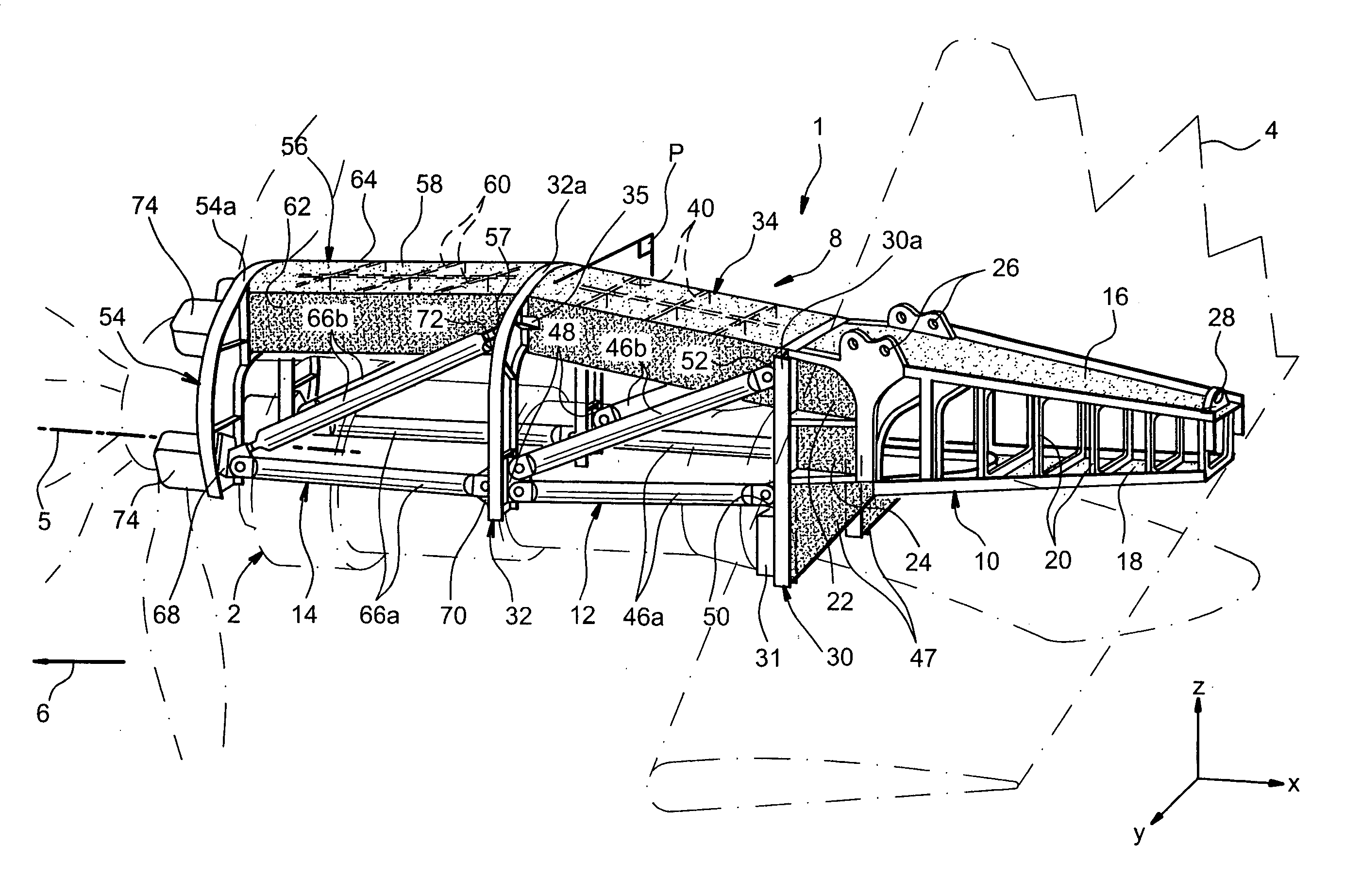
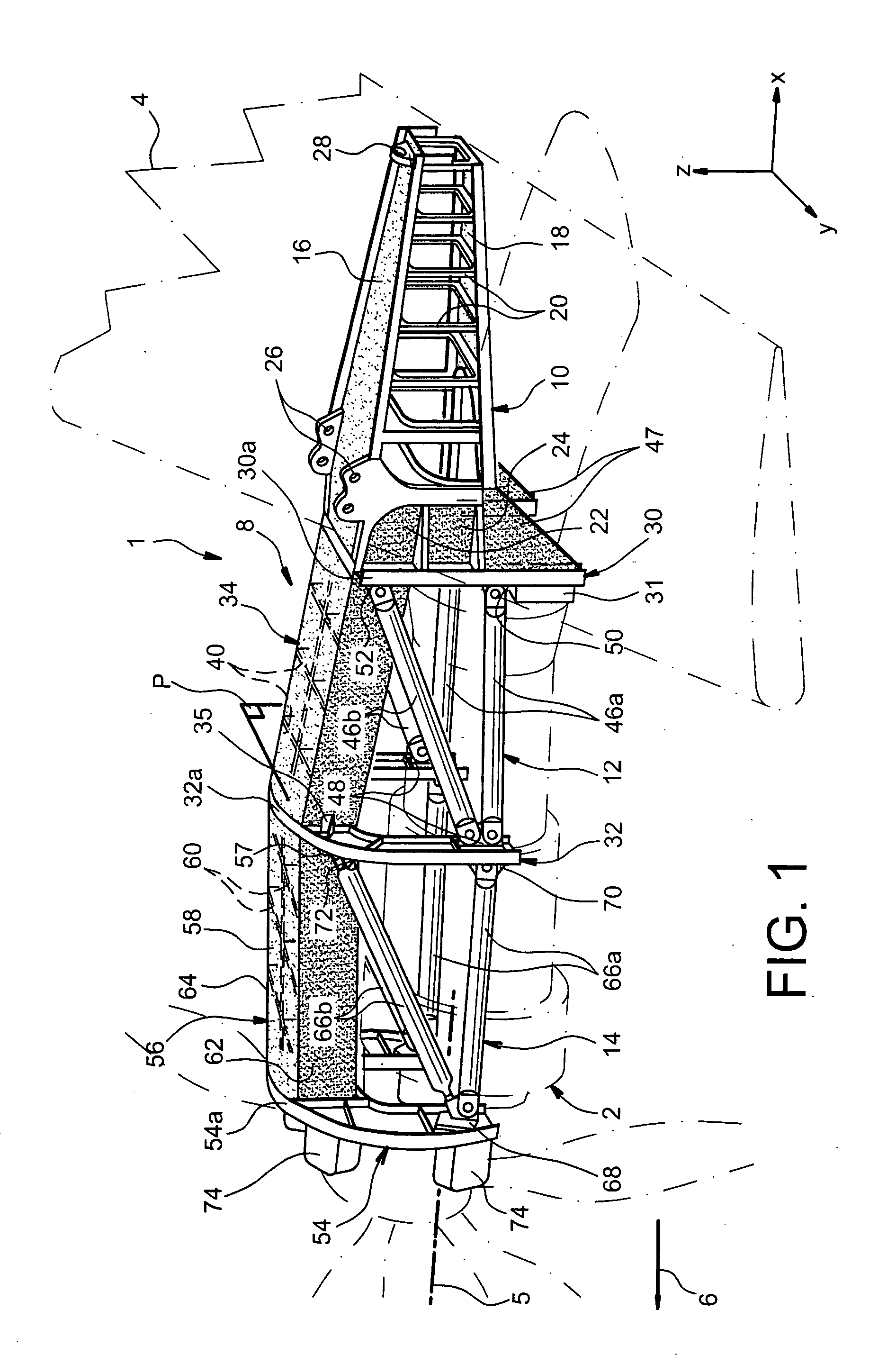
[0035]FIG. 1 shows a mounting structure 1 according to a first preferred embodiment of this invention, this structure 1 being designed to suspend a turboprop 2 under an aircraft wing shown only diagrammatically for obvious reasons of clarity, and generally denoted by the numeric reference 4.

[0036] Throughout the following description, by convention, X is the direction parallel to a longitudinal axis 5 of the turboprop 2, Y is the transverse direction relative to the aircraft, and Z is the vertical direction, these three directions being orthogonal to each other. Note that the longitudinal axis 5 of the turboprop 2 should be considered as being the longitudinal axis of the engine casing, and not the longitudinal axis of its propeller (not referenced).

[0037] Secondly, the terms “forward” and “aft” should be considered with respect to a direction of progress of the aircraft as a result of the thrust applied by the turboprops 2, this direction being shown diagrammatically by the arrow...


PUM


Abstract

This invention relates to a mounting structure (1) for mounting a turboprop (2) under an aircraft wing (4), the structure comprising a rigid structure (8) provided with an aft underwing box (10), and at least one forward rigid segment (12, 14), each forward rigid segment having two transverse frames (30, 32, 54) at a spacing from each other. According to the invention, at least one forward rigid segment (12, 14) of the rigid structure also comprises at least one forward upper box (34, 56) connecting a top part (30a, 32a, 54a) of the two transverse frames (30, 32, 54) of the forward rigid segment.

Description

TECHNICAL DOMAIN [0001] This invention relates to a structure for mounting or suspending a turboprop under an aircraft wing. [0002] This type of structure may be used on any type of aircraft comprising turboprops suspended under its wing. In this respect, it is particularly suitable for use on aircraft fitted with turboprops capable of outputting high power, more than 10000 horsepower. STATE OF PRIOR ART [0003] On existing aircraft, engines are suspended under or are mounted above the wing by complex Engine Mounting Structures (EMS). [0004] These structures are designed particularly to transmit static and dynamic forces generated by engines, such as weight, thrust or different dynamic forces, to the wing. [0005] In the special case of a turboprop, three main criteria are taken into account to design the associated mounting structure, namely resistance to engine torque, the mass of this structure and finally the limitation to the displacement of the turboprop nozzle relative to the m...

Claims


Application Information

Patent Timeline
IPC IPC(8): B64D27/12B64D27/18B64D27/26
CPCB64D27/12B64D2027/264B64D27/26
Inventor MACHADO, STEPHANECASSAGNE, JEROMEDEL BLANCO, ANTHONYMARTIN, YVONCHAMBREUIL, ARNAUD
Owner AIRBUS OPERATIONS (SAS)
Why Eureka
Try Eureka