
Tongue switch

a tongue switch and tongue technology, applied in the direction of rail switches, roads, constructions, etc., can solve the problems of affecting the service life of the tongue switch, the assembly must be replaced, and the movement of the tongue tends to wear the underlying surface of the assembly, so as to achieve convenient transportation, installation, replacement and maintenance.

Inactive Publication Date: 2005-06-02
VOESTALPINE NORTRAK
View PDF26 Cites 2 Cited by
  • Summary
  • Abstract
  • Description
  • Claims
  • Application Information

AI Technical Summary

Benefits of technology

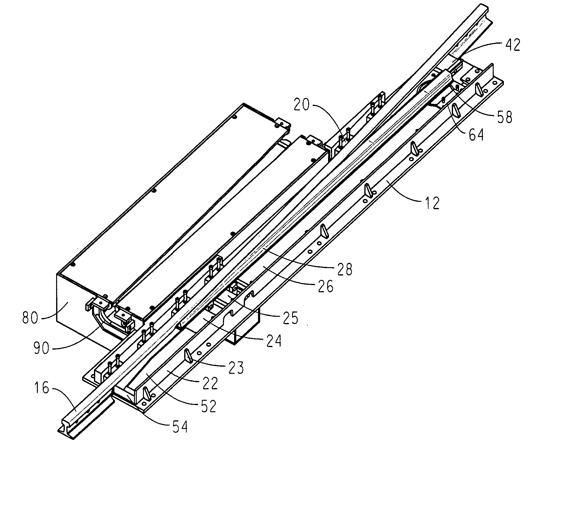
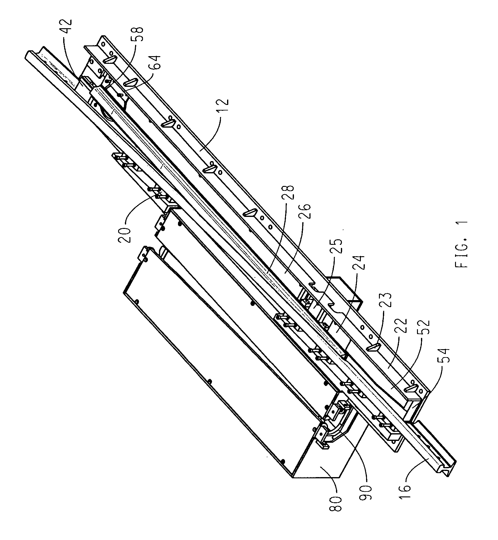
[0013] The invention provides a modular tongue switch assembly wherein the major components are individually removable and replaceable. The overall assembly is easily transported, installed, replaced and maintained, even when installed in an embedded or paved track system.
[0014] The tongue switch assembly has as its major replaceable parts a tongue, several non-contiguous slide surface plate sections and a stock rail. These replaceable parts all rest on top of the underlying bed and base plates. The tongue is pivotally connected at its heel to one of the slide surface plate sections. A pivot retainer, consisting of a flat piece bolted down over the edge of the tongue heel, prevents displacement of the tongue from the pivot point when trains pass over the tongue. Upon removal of the pivot retainer, the tongue can be removed from the assembly for repair or replacement. The surfaces of the slide plate sections are finely machined, reducing the need for lubricant while still ensuring the tongue moves smoothly across the slide plate sections.
[0015] The slide plate sections are removably bolted to corresponding bed plate sections. The bed plate sections are welded to the base plate. These plates together provide strength and stability for the tongue switch assembly. The bed plate sections are narrower than the base plate and rest against the inner web of the stock rail, providing support and helping to keep the stock rail in position.
[0016] The stock rail is seated in a rail seat machined into the base plate. Floating brace block assemblies are bolted over the base and against the outer web of the stock rail, holding the stock rail in proper position. The floating brace block assemblies consist of a brace and a wedge block, bolted into place against a wedge block support welded to the base plate. This method of positioning and holding the stock rail in place allows relatively quick and simple removal of the stock rail, if necessary.
[0017] The invention also provides a novel inner and outer switchbox assembly that allows a conductor rail to be repositioned along with the tongue. The inner switchbox moves with the tongue, guided by a lever arm and rodding between the tongue and the inner switchbox. The conductor rail runs through the inner switchbox, and thus also moves with the tongue. This allows the train collector to maintain contact with the conductor rail at all points throughout the turn. The inner switchbox is a formed piece with welded ends, making it relatively easy to construct. Most of the switchbox assembly is completed before the tongue switch assembly is shipped to the customer, reducing installation time. The lever arm and rodding assembly between the tongue and the inner switchbox is placed on the field side of the box assembly. It is also placed horizontally, allowing access to both ends of the lever arm, to facilitate proper adjustment of the components of the box assembly. Any connections that must be made or adjusted in the field are thus relatively simple and accessible, further reducing maintenance and down time for the track.

Problems solved by technology

This arrangement gives rise to certain difficulties.
Movement of the tongue tends to wear the underlying surface of the assembly.
If the wear becomes such that replacement is required, the entire assembly must be replaced.
However, passage of the train over the cover plate tends to wear the cover plate and its hold down points.
However, the application and replacement of lubricant is costly and time-consuming.
However, once the coating has worn away or if the slide surface itself is damaged, the entire assembly must be replaced.
Slide chair or roller assemblies are more complex than simply applying lubricant, and they must frequently be replaced.
In such systems, the tongue switch assembly is embedded in pavement or concrete, making it difficult to replace or maintain the switch.
Embedded tongue switch assemblies also present an additional problem when used in association with electric locomotives.
However, such location of the lever arm would present particular difficulties in maintaining or replacing the lever arm.
Access to the lever arm is difficult in that the entire switchbox must be disengaged and removed from its embedded position along with portions of the trackwork or the tongue switch assembly.
In addition, it has been proposed to cast the outer shell of the movable switchbox as a single aluminum piece for ease of installation, but this would make it relatively weak and difficult to manufacture.

Method used


Image

  • Tongue switch
  • Tongue switch
  • Tongue switch

Examples


Embodiment Construction

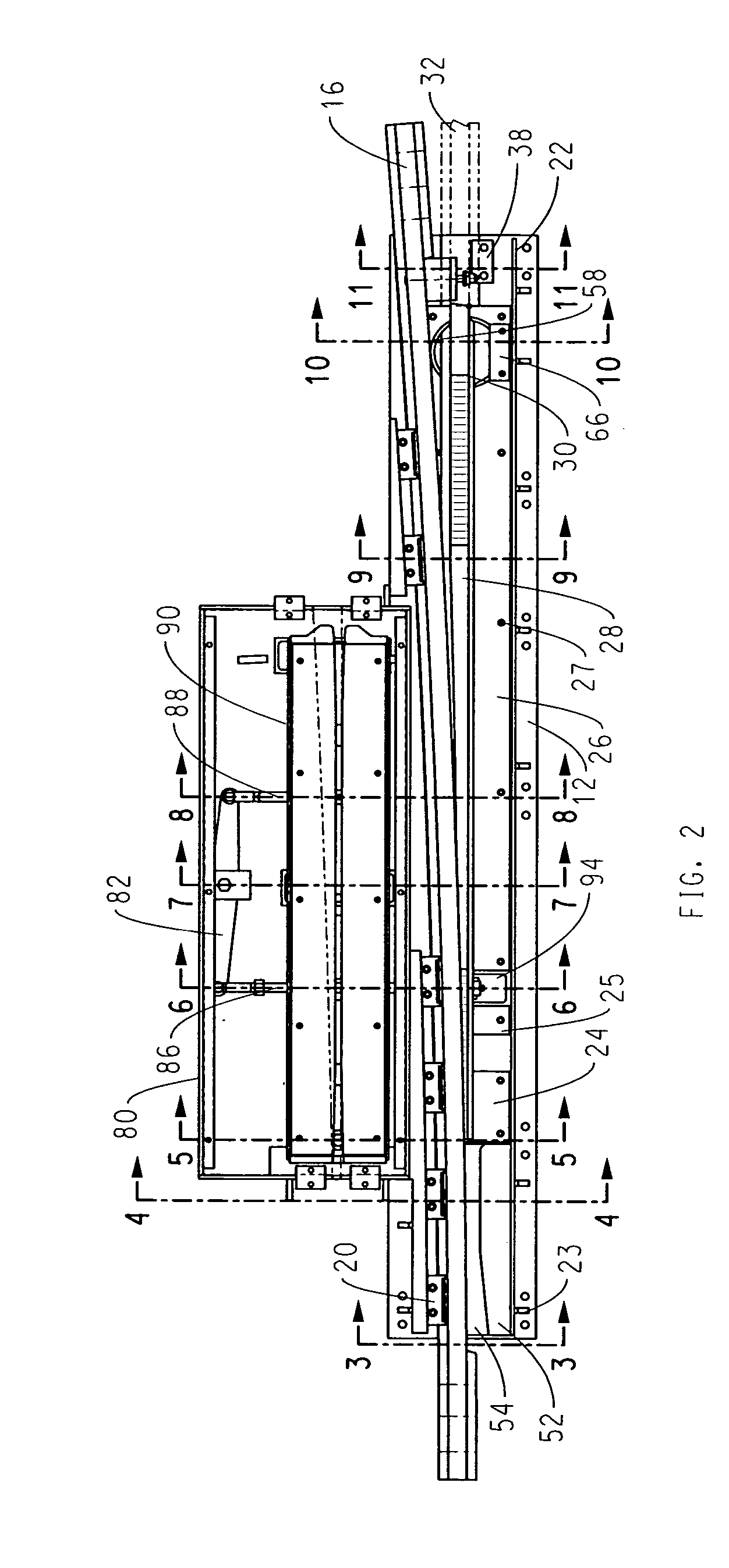
[0046]FIGS. 1, 2 and 2a show the preferred embodiment of the assembly of the invention, as inserted into a section of embedded or paved trackwork, for use with an electrically-powered train.

[0047] The switch generally rests on base plate 12. Bed plate sections 13, 14, 15 are welded on top of base plate 12, as seen in FIG. 12. Stock rail 16 is seated on base plate 12 and is held in place by rail seat 18 that has been machined into base plate 12 and by floating brace block assemblies 20, as seen in FIG. 3. Referring again to FIGS. 1, 2, and 2a, concrete barrier plate 22 keeps the surrounding concrete out of the switch. Gussets 23 stiffen concrete barrier plate 22. Slide plate sections 24, 25, 26 are bolted on top of corresponding bed plate sections 13, 14, 15 by bolts 27 (see FIGS. 5 and 7 for illustrations of the connections between slide plate sections 24, 26 and base plate sections 13, 15 respectively). A tongue 28, pivoted at its heel 30, pivots across the surface of slide plate ...


PUM


Abstract

A modular tongue switch assembly comprises a tongue pivotally connected to a slide surface, held down by a pivot retainer. The slide surface consists of slide plate sections removably attached to corresponding bed plate sections, which are in turn welded onto a base plate. Floating brace blocks hold a non-integral stock rail in place on the base plate. When the tongue moves, a horizontal lever arm actuates an inner box assembly housed within an outer box and containing the conductor rail, allowing the passing train to maintain contact with the conductor rail, if necessary. A novel rodding and lever arrangement is used.

Description

TECHNICAL FIELD OF THE INVENTION [0001] This invention relates to a tongue switch assembly for use in embedded or paved railway track systems. BACKGROUND OF THE INVENTION [0002] Prior art tongue switch assemblies typically involve a single cast piece that includes flangeways, turnout rail segments and closure rail segments, with the principal separate and removable component being the tongue itself. This arrangement gives rise to certain difficulties. Movement of the tongue tends to wear the underlying surface of the assembly. If the wear becomes such that replacement is required, the entire assembly must be replaced. [0003] One method used to connect the tongue to the underlying assembly is by pivoting it about the heel end (see e.g. U.S. Pat. No. 2,377,273 to Siebert). The pivot point consists of a pin extending downward from the tongue and inserted into a recess in the underlying switch base. A bearing surface is sometimes provided between the pin and the recess (see, e.g. U.S. P...

Claims


Application Information

Patent Timeline
IPC IPC(8): E01B7/04
CPCE01B7/04
Inventor O'BRIEN, CORYCLICK, GARY
Owner VOESTALPINE NORTRAK
Learn More