
Article of footwear comprising a unitary support structure and method of manufacture

a unitary support and footwear technology, applied in the field of footwear, can solve the problems of time and labor, increased cost of an already expensive process, and inability to meet the requirements of quality assurance measures, and achieve the effect of avoiding the necessity of quality assurance measures and reducing the cost of manufacturing

Active Publication Date: 2005-06-02
BAUER HOCKEY LLC
View PDF14 Cites 50 Cited by
  • Summary
  • Abstract
  • Description
  • Claims
  • Application Information

AI Technical Summary

Benefits of technology

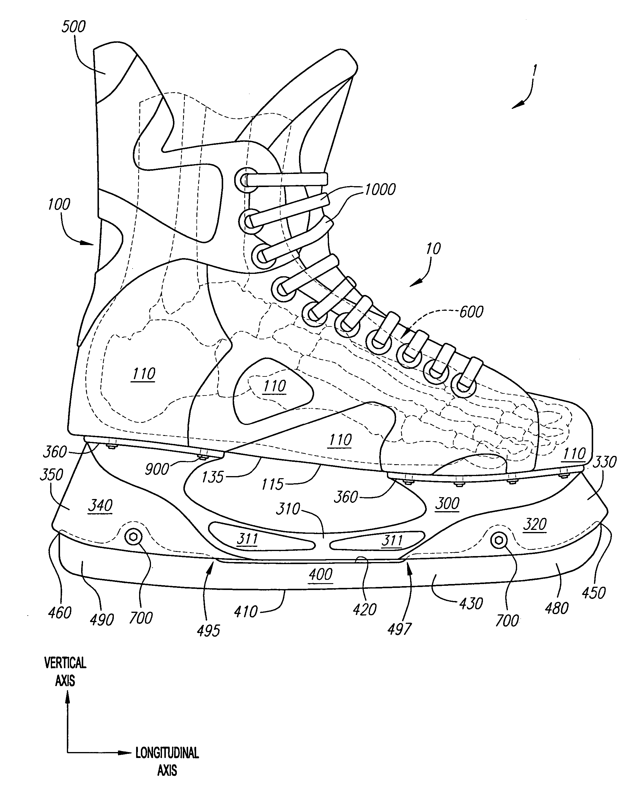
The present invention is about an article of footwear with a unique support structure made up of multiple wall structures. These wall structures can be positioned and combined with each other to create a custom fit for the foot. The support structure is made of a non-isotropic material made of aligned fibers in a hardened resin matrix, which allows for flexibility and flexibility in different directions. The upper portion of the footwear is also made of a pliable material that overlaps and attaches to the support structure, providing further stability and support. The invention also includes methods for manufacturing the support structure and the resultant product. Overall, the invention allows for a customizable, stable, and comfortable article of footwear.

Problems solved by technology

The lasting process, however, is time and labor intensive.
Consequently, manufacturers have often implemented stringent quality assurance measures, which result in additional cost to an already expensive process.
Nor can such quality assurance measures necessarily avoid the inherent dimensional inconsistency that is endemic to the lasting process; such that seemingly identical footwear having the same manufactured size, nevertheless fit or feel noticeably different.
Furthermore, lasted footwear products, like baseball gloves, often require significant break-in time in order to provide the desired flexibility and fit.
Once broken-in, continued use of the ice skate, however, may often result in the ice skate being physically degraded to the point where it no longer provides the needed support or stiffness in the desired areas, such as at or about regions configured to surround the ankle and the outward protrusions created by the lateral and medial malleolus bone formations.
Moreover, the employment of additional layers of textile materials to fortify the walls of the article of footwear often adds significant weight and bulk.
Furthermore, because optimum performance is achieved between the period of break-in and degradation, performance is transient with time and use.
Engineering unitary injected molded plastic shell structures, therefore, is primarily limited to (1) the choice of plastic material(s), (2) the design of the external and internal configuration of the shell, and (3) the manipulation of the thickness of the chosen plastic material at any given location in the shell.
As a consequence, the more substantial the shell component, the more difficult it is to design and the less likely it will provide the wearer with the desired performance.
On the other hand, employment of a less substantial shell component tends to negate both the shell's ability to define end-shape and foot cavity volume as well as the likelihood of realizing significant manufacturing efficiencies relative to the lasting process.
To make matters worse, experience has shown that many consumers find such injected molded plastic shell structures to be aesthetically displeasing or otherwise indicative of poor craftsmanship.
Consequently, such articles of footwear are subject to the additional expense associated with concealing the plastic shell within more aesthetically pleasing textile materials.
Moreover, because such plastic shell structures are rigidly formed to provide a defined end-shape and foot cavity volume while also providing firm support to the foot, such shell structures have an inherent disadvantage in facilitating flexibility vis-à-vis lasted footwear, which are generally formed of layers of pliable components.
Although, there has been numerous and continuing attempts to design and implement injected molded plastic shell structures to form non-lasted articles of footwear, such attempts have generally not sufficiently overcome the significant aforementioned design hurdles and as a result have been met with limited consumer acceptance.

Method used


Image

  • Article of footwear comprising a unitary support structure and method of manufacture
  • Article of footwear comprising a unitary support structure and method of manufacture
  • Article of footwear comprising a unitary support structure and method of manufacture

Examples


example application no.1

Example Application No. 1 of Formulas (1) through (3)

[0172] Suppose that L-HB measures eight (8 ) inches then the PLR, MPLR, and EMPLR according to formulas (1) through (3), as previously set forth, are:

L-HBPLRMPLREMPLR8 inches+ / −2.4 inches+ / −1.2 inches+ / −0.6 inches

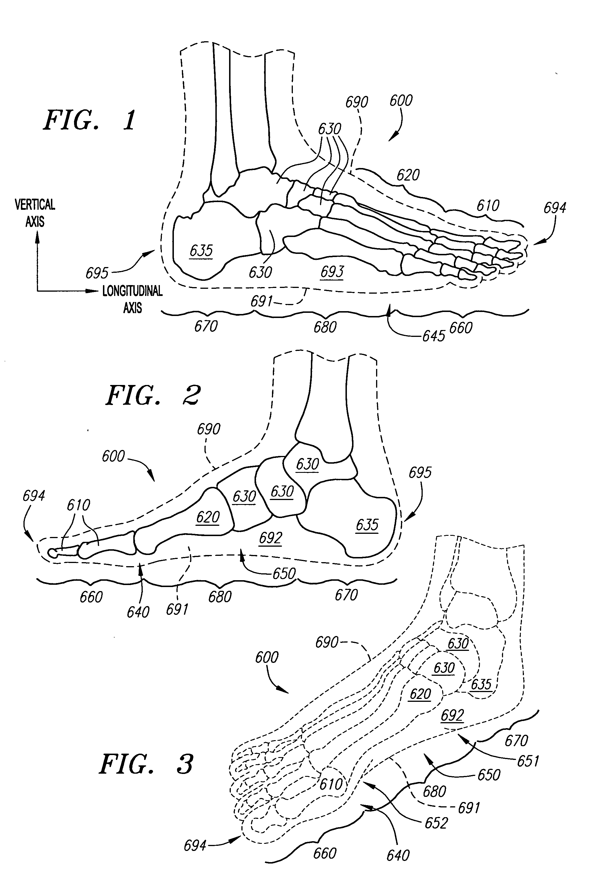
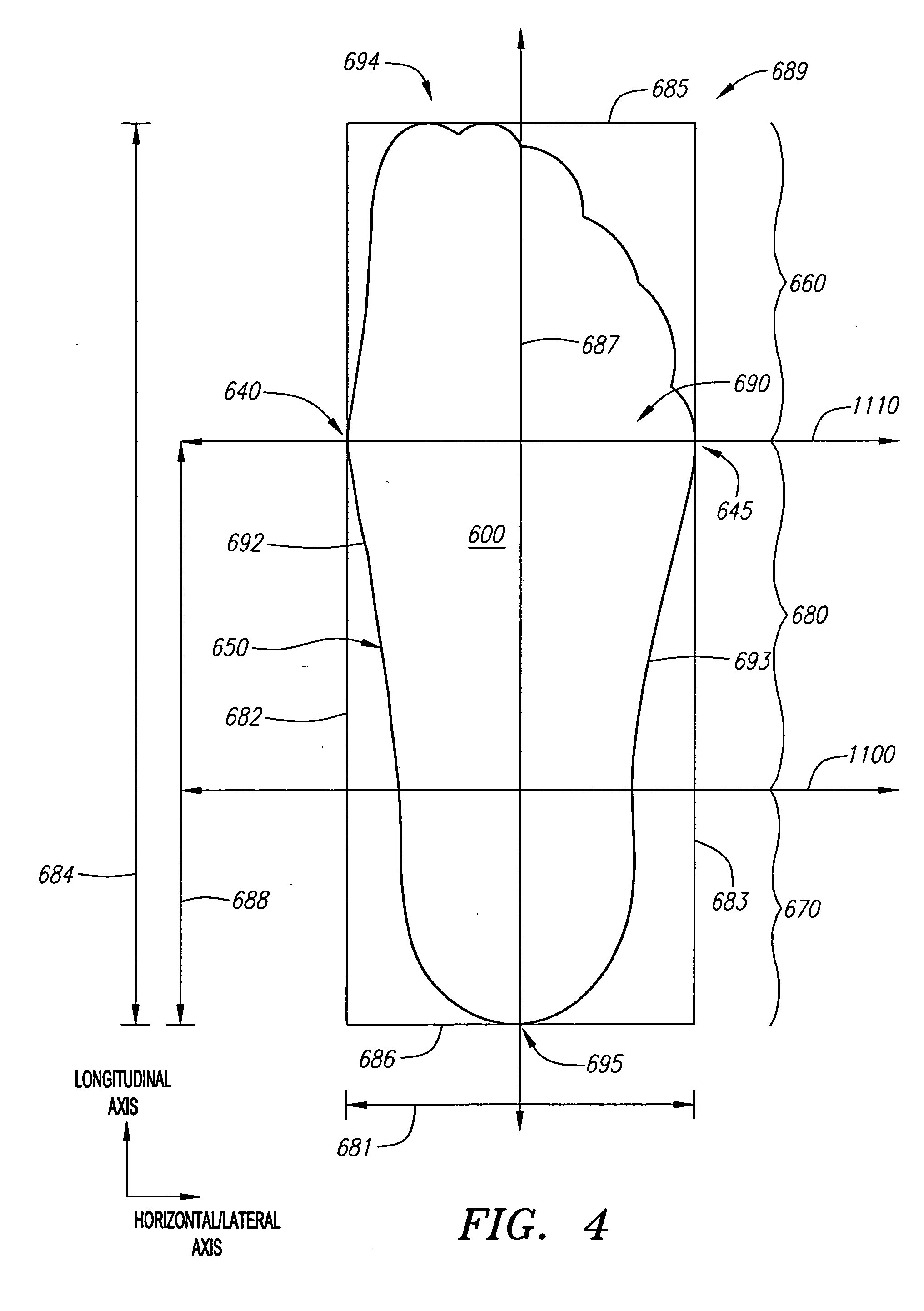
[0173] Vis-à-vis terminal end points 166 and 182 and longitudinal partitions 161, each of those preferred longitudinal location ranges is centered at the anterior end 651 of the heel region 670. Accordingly, taking the longitudinal length of heel region 670 as constituting 40% of the L-HB then the anterior end 651 of the heel region 670 would be located 3.2 inches (40% of 8 inches) anterior from the back of the heel region 670. The preferred longitudinal location of terminal end point 166 and 182 and longitudinal partitions 161 would thus be:

Anterior End ofAnterior End ofAnterior End ofHeel + / − PLRHeel + / − MPLRHeel + / − EMPLR3.2 inches + / − 2.4 inches3.2 inches + / − 1.2 inches3.2 inches + / − 0.6inches

[0174] In order to fu...

example application no.2

Example Application No. 2 of Formulas (1) through (3)

[0179] Suppose again that L-HB measures eight (8) inches. The PLR, MPLR, and EMPLR, according to formulas (1) through (3), would thus be the same as previously set forth in Example Application No. 1. The preferred longitudinal location of terminal end points 167 and 181 and longitudinal partitions 162 vis-à-vis the ball of the foot 640 would thus be:

Ball of theBall of the Foot + / − PLRBall of the Foot + / − MPLRFoot + / − EMPLR8 inches + / − 2.4 inches8 inches + / − 1.2 inches8 inches + / − 0.6inches

[0180] With reference to FIG. 26 the longitudinal center of the ranges PLR, MPLR, and EMPLR on the medial and lateral sides 140, 150 of the sole 115 would be centered on horizontal axis line 1110, which as previously described corresponds with the ball of the foot 640 and the lateral extent of the foot 645. Accordingly, by way of example, if terminal end point 167 or 181 is located on the unitary support structure 110 between 5.6 inches and 10....


PUM

PropertyMeasurementUnit
longitudinal lengthaaaaaaaaaa
distanceaaaaaaaaaa

Abstract

An article of footwear comprising a molded unitary support structure preferably constructed of substantially continuous fibers aligned in one or more defined orientations disposed within a hardened resin matrix and methods of manufacturing is disclosed. The unitary support structure comprises a plurality of wall structures including a sole that extends generally from a front end region configured to underlie the toe region of the foot to a back end region configured and side wall structures that extend from the sides of the sole. The wall structures are partitioned from one another to facilitate flex and provide structural and functional independence between partitioned regions. The vertical and longitudinal locations of the partitions are configured to coincide with defined locations relative to the foot so as to facilitate natural movement bending in the foot while also providing the needed support as well as the desired flexibility in attached ground engaging structures. An upper portion overlies and conforms to the wall structures of unitary support structure and extends from its perimeter regions to further encapsulate the foot and provide comfort, fit and performance traditionally obtained from lasted articles of footwear. A preferred method of manufacture includes the steps of forming a male mold, overlaying it with plies of substantially continuous groups of aligned fibers oriented in defined directions to form an uncured pre-form construct of the unitary support structure, which is then cured in a female mold, partitioned and incorporated into an article of footwear. Regions of the wall structures including the sole may be formed to include variations in strength, flexibility and / or elastic modulus in one or more directions.

Description

RELATED APPLICATIONS [0001] This applications claims the benefit of priority of U.S. Provisional Application Ser. No. 60 / 501,752 filed on Sep. 10, 2003, the entirety of which is hereby incorporated by reference.FIELD OF THE INVENTION [0002] The field of the present invention relates to footwear such as ice skates and more particularly to the configuration and construction of footwear employing unitary support structures and even more particularly to the configuration and construction of footwear employing unitary molded support structures comprising a construction of substantially continuous fibers aligned in one or more defined orientations and disposed within a hardened resin matrix. BACKGROUND OF THE INVENTION [0003] Footwear such as shoes, boots, ice and roller skates and the like are commonly fabricated by employing a method referred to in the shoe industry as “lasting.” The process is referred to as lasting because the article of footwear is formed over a “last,” which is a th...

Claims


Application Information

Patent Timeline
Patent Type & Authority Applications(United States)
IPC IPC(8): A43B5/16B29C70/34B29C70/44B29D35/00B29D35/04B29D35/14
CPCA43B5/1625A43B5/1641A43B5/1666A43B5/1683A43B5/1691B29C70/207B29L2031/50B29C70/345B29D35/04B29D35/126B29D35/128B29D35/146B29D35/148B29C70/342
Inventor GOLDSMITH, EDWARD M.HALKO, ROMAN D.CHARTRAND, DANIELWENSLEY, NEIL
Owner BAUER HOCKEY LLC
Learn More