Corrugated gasket core with profiled surface

a gasket core and corrugated metal technology, applied in the field of corrugated gasket cores, can solve the problems of lack of resiliency seen in limited shear resistance, and inability of corrugated metal gasket cores to withstand high internal pressure, so as to improve the contribution to the art

Inactive Publication Date: 2005-06-02
GARLOCK SEALING TECHNOLOGIES
View PDF5 Cites 58 Cited by
  • Summary
  • Abstract
  • Description
  • Claims
  • Application Information

AI Technical Summary

Benefits of technology

[0010] As will be realized by those of skill in the art, many different embodiments of a gasket according to the present invention are possible. Additional uses, objects, advantages, and novel features of the invention are set forth in the detailed description that follows and will become more apparent to those skilled in the art upon examination of the following or by practice of the invention.
[0011] Thus, there has been outlined, rather broadly, the more important features of the invention in order that the detailed description that follows may be better understood and in order that the present contribution to the art may be better appreciated. There are, obviously, additional features of the invention that will be described hereinafter and which will form the subject matter of the claims appended hereto. In this respect, before explaining several embodiments of the invention in detail, it is to be understood that the invention is not limited in its application to the details and construction and to the arrangement of the components set forth in the following description or illustrated in the drawings. The invention is capable of other embodiments and of being practiced and carried out in various ways.
[0012] It is also to be understood that the phraseology and terminology herein are for the purposes of description and should not be regarded as limiting in any respect. Those skilled in the art will appreciate the concepts upon which this disclosure is based and that it may readily be utilized as the basis for designating other structures, methods and systems for carrying out the several purposes of this development. It is important that the claims be regarded as including such equivalent constructions insofar as they do not depart from the spirit and scope of the present invention.
[0013] So that the manner in which the above-recited features, advantages and objects of the invention, as well as others which will become more apparent, are obtained and can be understood in detail, a more particular description of the invention briefly summarized above may be had by reference to the embodiment thereof which is illustrated in the appended drawings, which drawings form a part of the specification and wherein like characters of reference designate like parts throughout the several views. It is to be noted, however, that the appended drawings illustrate only preferred and alternative embodiments of the invention and are, therefore, not to be considered limiting of its scope, as the invention may admit to additional equally effective embodiments.

Problems solved by technology

One substantial limitation of this design is the inability of the gasket to withstand high internal pressures.
This failure occurs in part because the gasket material does not sufficiently mechanically bond to the metal substrate, and therefore has a limited amount of shear resistance to overcome high internal system pressures.
However, a drawback to the profiled design is the lack of resiliency seen in the corrugated metal gaskets.
Because of this lack of resiliency, the sealing forces in the flanges connection will degrade over time due to the tendency of the soft gasket material to creep or take compression set.

Method used


Image

  • Corrugated gasket core with profiled surface
  • Corrugated gasket core with profiled surface
  • Corrugated gasket core with profiled surface

Examples


Embodiment Construction

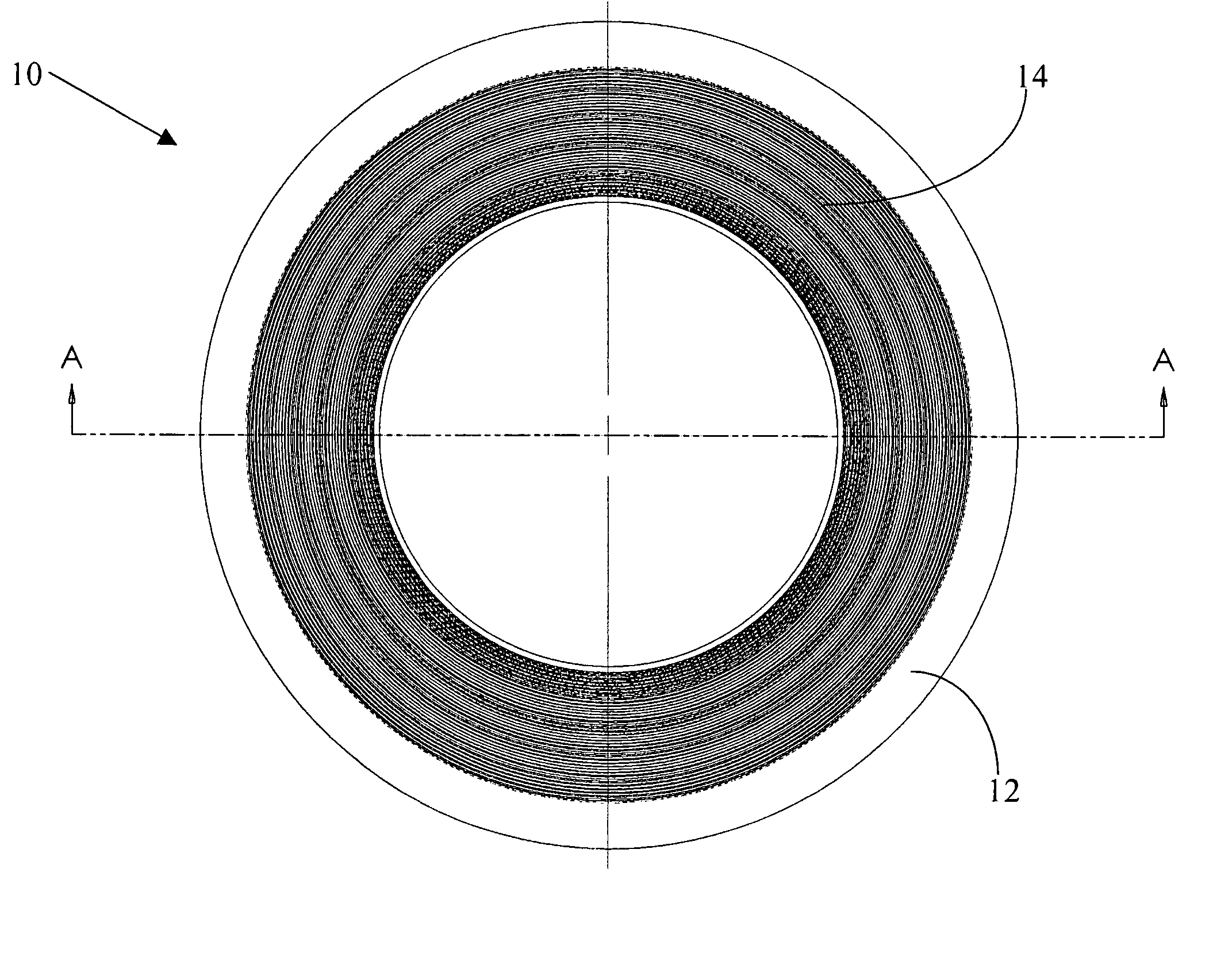
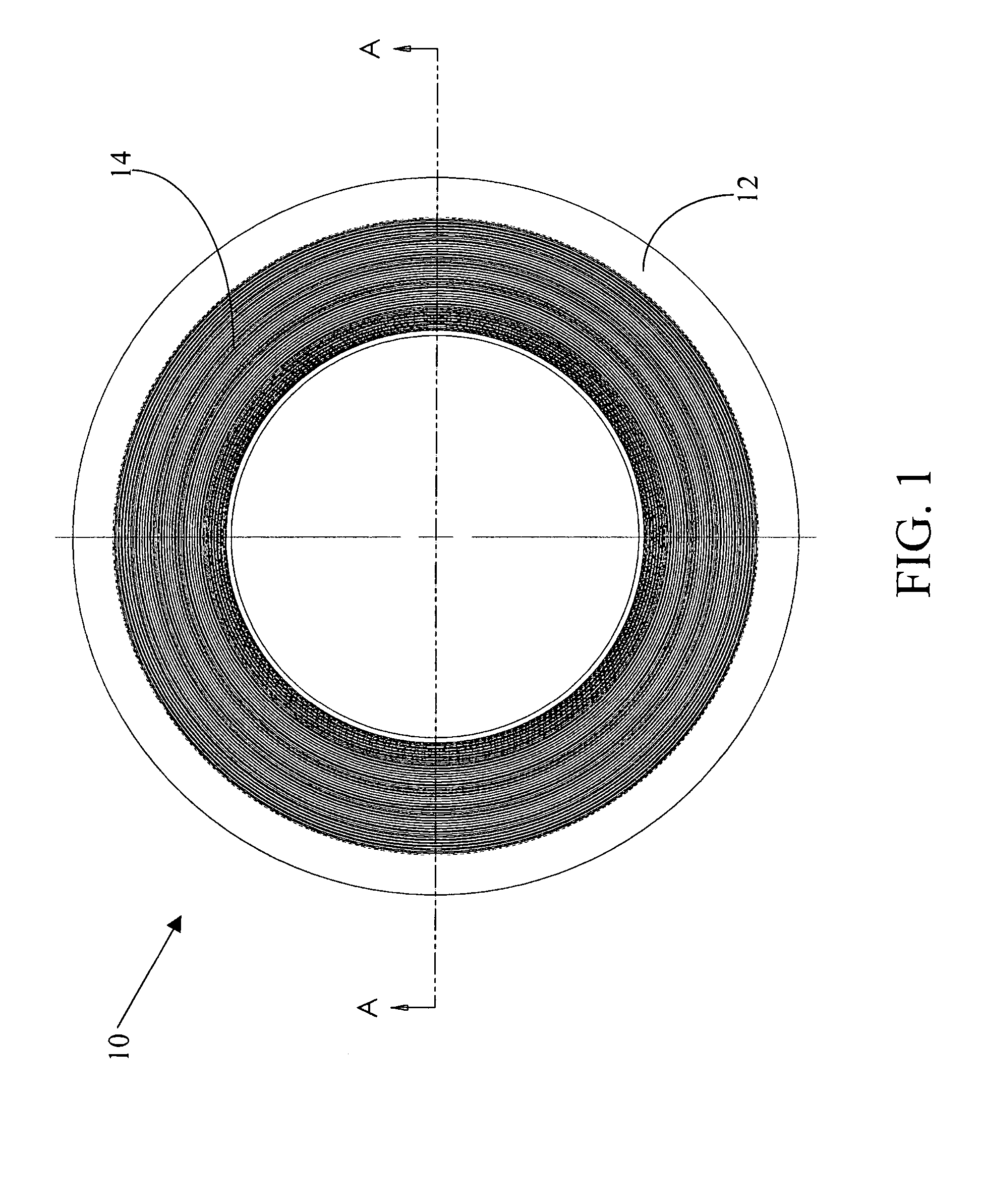
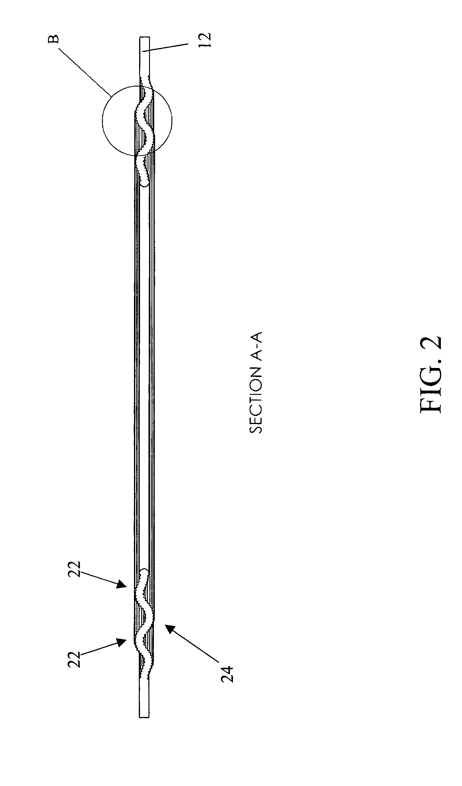
[0018] In a first aspect of the present invention, a gasket is provided comprising a rigid core having corrugations formed therein and two profiled faces, the core being encapsulated by a gasketing material. In a preferred embodiment of the present invention, the profiled faces comprise a series of concentric peaks and grooves formed in the gasket surface to a predetermined depth. In a further preferred embodiment of the present invention, the corrugations comprise a sinusoidal pattern of concentric peaks and valleys formed through the entire thickness of the core material such that the second face of the gasket has the opposing corrugation pattern (peaks and valleys) of the first.

[0019] Referring to the figures, a gasket 10 according to an embodiment of the present invention is shown comprising a core material 12 which is at least partially encapsulated with a gasketing material 14. The core material 12 is corrugated from the inner diameter through a portion of the material. The c...


PUM


Abstract

A gasket is provided comprising a gasket core having an outer portion and an inner portion defining an aperture, and opposing first and second faces, wherein at least a portion of the core is corrugated through its thickness and at least one face is at least partially profiled, and a gasketing material disposed upon said at least one partially profiled face. The profiling comprises a series of concentric grooves formed into the core material and the corrugation preferably comprises a sinusoidal-shaped wave comprising concentric rings of peaks and valleys.

Description

CROSS REFERENCE TO RELATED APPLICATIONS [0001] The present application claims priority under 35 U.S.C. § 119(e) from U.S. Provisional Patent Application Ser. No. 60 / 524,748 filed Nov. 25, 2003, entitled “Gasket With Serrated Surface and Corrugated Core”, the disclosure of which is incorporated herein by reference.FIELD OF THE INVENTION [0002] The present invention relates to gaskets for sealing the juncture between opposing flanges. More particularly, the present invention relates to gaskets having a semi-rigid substrate comprising opposing faces that are both profiled and corrugated. BACKGROUND OF THE INVENTION [0003] Corrugated metal gaskets are comprised of a thin gauge metal substrate that is corrugated, then covered with a soft gasket material. Examples of these gaskets are illustrated in U.S. Pat. Nos. 5,421,594; 5,785,322; and 6,092,811 all of which are hereby incorporated by reference. The corrugated metal design provides greater resiliency than the flat homogeneous gasket m...

Claims


Application Information

Patent Timeline
Patent Type & Authority Applications(United States)
IPC IPC(8): F16J15/08F16J15/12F16L23/22
CPCF16J15/0818F16J15/122F16L23/18
Inventor SEIDEL, FRANCISDAVIS, RICHARDREID, DAN
Owner GARLOCK SEALING TECHNOLOGIES
Why Eureka
Try Eureka