System and method for imaging regions of interest

Inactive Publication Date: 2005-06-02
AGILENT TECH INC
View PDF2 Cites 29 Cited by
  • Summary
  • Abstract
  • Description
  • Claims
  • Application Information

AI Technical Summary

Benefits of technology

[0012] Advantageously, embodiments of the present invention increase the imaging speed when only a subset of the complete field-of-view is transmitted to the image processing application. Likewise, the image data transfer rate is improved by transmitting only a portion of the image data. In addition, the frame rate can also be increased by reading out only a portion of the image data directly from the image sensor. Furthermore, the invention provides embodiments with other features and advantages in addition to or in lieu of those discussed above. Many of these features and advantages are apparent from the description below with reference to the following drawings.

Problems solved by technology

The high volume of image data unrelated to the ROI segments that is transmitted from the camera necessarily increases the processing time and the complexity of such image processing systems.
However, current CMOS image sensors do not provide the ability to image a single irregular-shaped ROI or multiple ROI segments that are spatially separated with respect to one another in a single image frame.

Method used


Image

  • System and method for imaging regions of interest
  • System and method for imaging regions of interest
  • System and method for imaging regions of interest

Examples


Embodiment Construction

[0037] The numerous innovative teachings of the present application will be described with particular reference to the exemplary embodiments. However, it should be understood that these embodiments provide only a few examples of the many advantageous uses of the innovative teachings herein. In general, statements made in the specification do not necessarily delimit any of the various claimed inventions. Moreover, some statements may apply to some inventive features, but not to others.

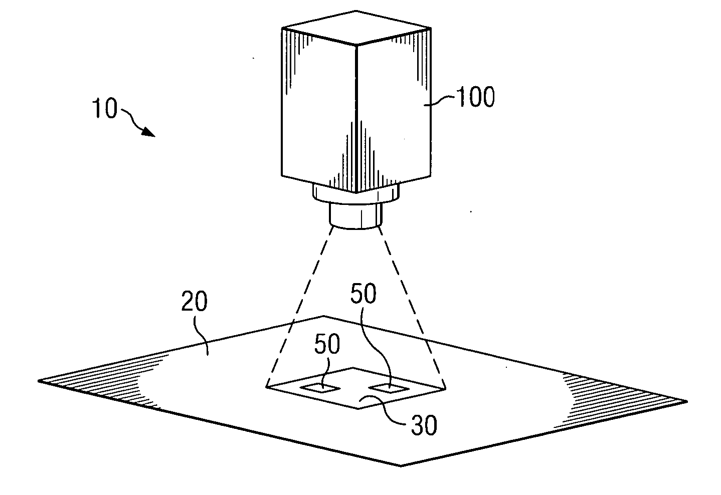
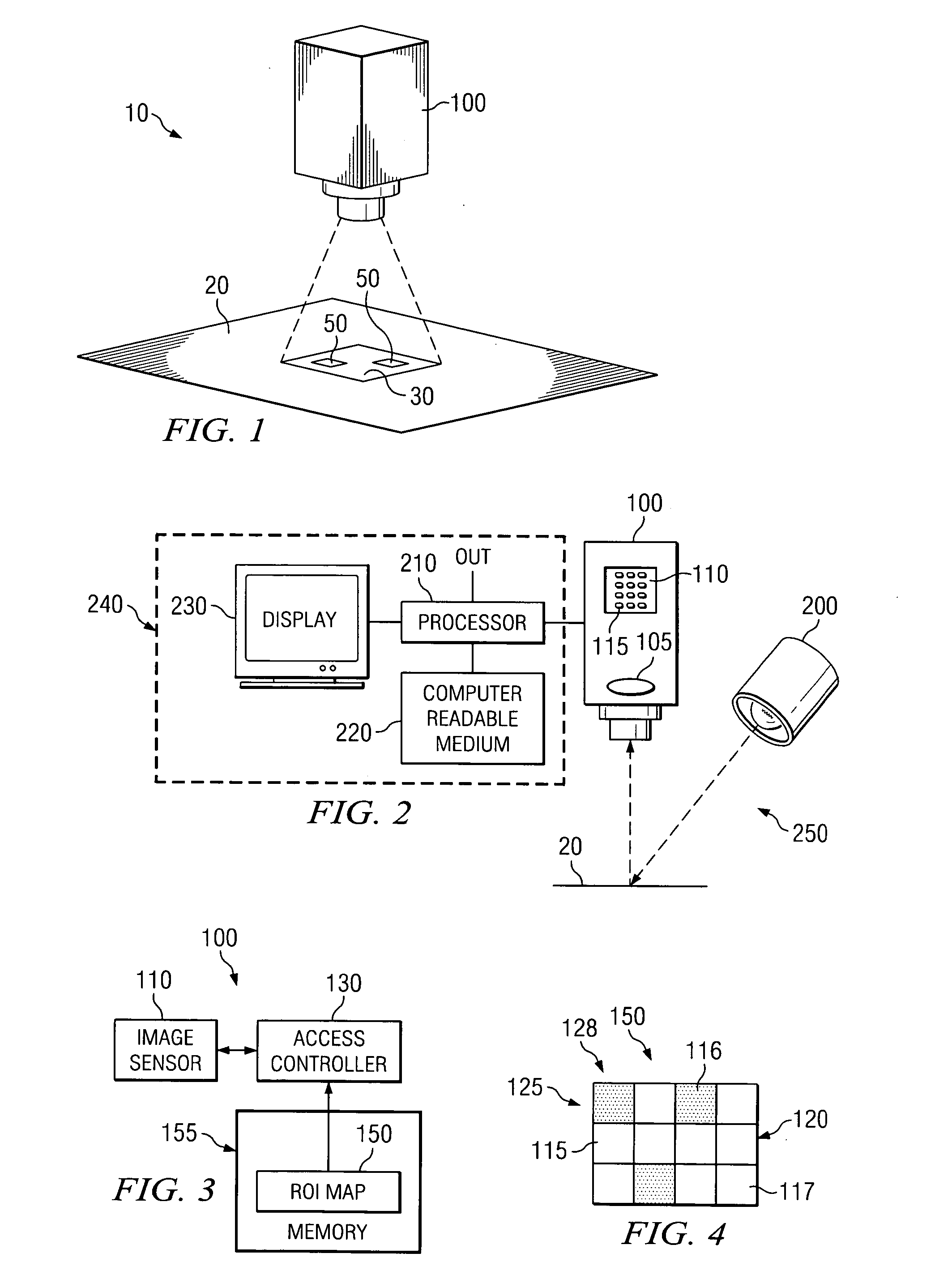
[0038]FIG. 1 illustrates a perspective view of a simplified exemplary imaging system 10 capable of imaging two or more region of interest segments (ROI segments) 50 on a target surface 20 within a field of view (FOV) 30 of a camera 100, in accordance with embodiments of the present invention. The target surface 20 can be, for example, a printed circuit board having a multitude of features, such as solder joints and components, thereon. Each image captured can contain multiple ROI segments 50 within the...


PUM


Abstract

A camera uses a map to retrieve image data pertaining to two or more region of interest segments (ROI segments) within the field-of-view (FOV) of the camera. The map identifies selected pixels of the image located in the region of interest segments. Image data corresponding to the image can be stored and the image data associated with the selected pixels can be accessed individually. In other embodiments, image data associated with the selected pixels is read off of the image sensor row-by-row or pixel-by-pixel. The camera can be included within an optical inspection system to analyze ROI segments on a target surface by transmitting only the image data associated with the ROI segments from the camera to an image processing system of the optical inspection system.

Description

BACKGROUND OF THE INVENTION [0001] 1. Technical Field of the Invention [0002] The present invention relates generally to imaging systems, and more particularly, to cameras capable of imaging regions of interest within an image. [0003] 2. Description of Related Art [0004] A camera is used to capture an image of a scene within the field-of-view (FOV) of the camera. The FOV is determined by the magnification of the camera lens and by the dimensions of the image sensor. Within a particular scene, there may be one or more features that are of interest to the camera operator or the application using the camera. A spatial area within the FOV that outlines a particular relevant feature is known as a region of interest (ROI). [0005] In many image processing applications, the ROI within a scene is smaller than the FOV. Multiple ROI segments may also exist in within the FOV. Under these circumstances, the amount of information that is captured and transmitted by the camera can be significantly...

Claims


Application Information

Patent Timeline
IPC IPC(8): H04N7/18
CPCG01N21/88
Inventor BAER, RICHARD L.
Owner AGILENT TECH INC
Why Eureka
Try Eureka