Fixing apparatus

Active Publication Date: 2016-11-10
CANON KK
View PDF2 Cites 5 Cited by
  • Summary
  • Abstract
  • Description
  • Claims
  • Application Information

AI Technical Summary

Benefits of technology

The invention is a device that helps speed up image forming devices while reducing the occurrence of unwanted electrical effects.

Problems solved by technology

However, increase in power supplied to a heater makes it difficult to suppress the occurrence of harmonic current and flicker.

Method used


Image

  • Fixing apparatus
  • Fixing apparatus
  • Fixing apparatus

Examples


first embodiment

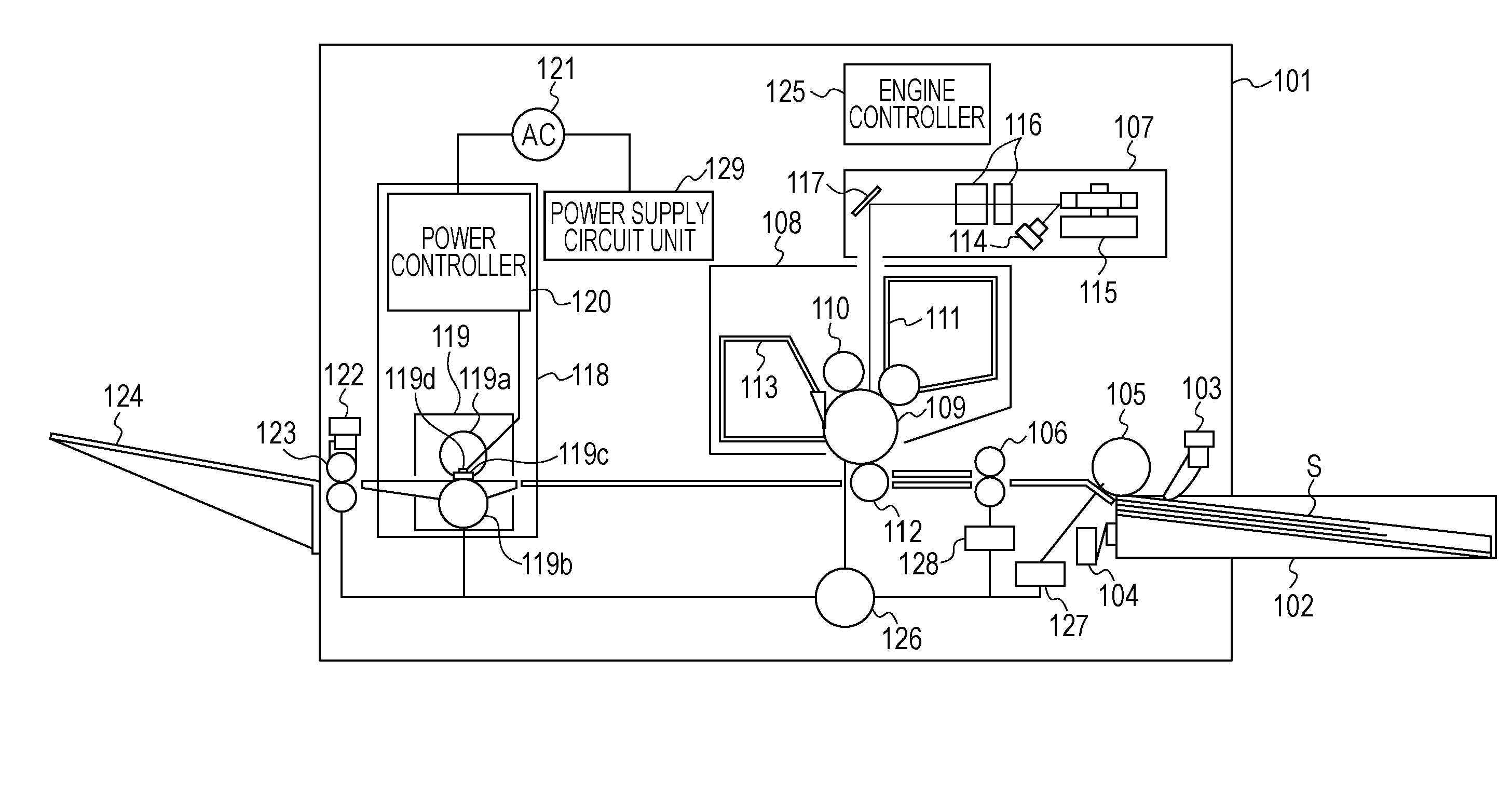
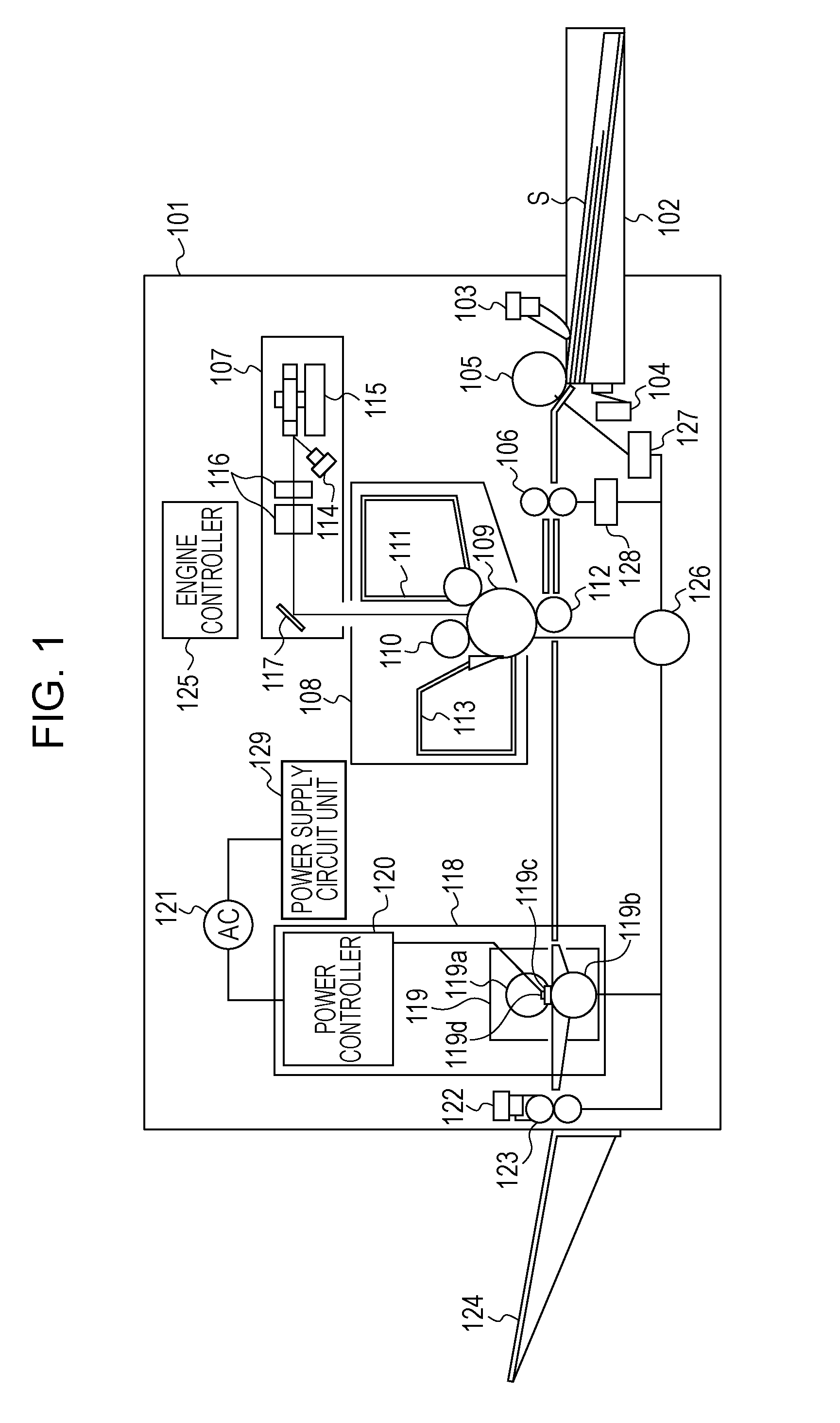
[0024]FIG. 1 is a schematic view of the configuration of an image forming apparatus (printer) which performs printing by using the electrophotographic recording technology. A printer main body 101 includes a cassette 102 storing a recording medium S. The printer main body 101 also includes a recording-medium detecting sensor 103 which detects the presence of the recording medium S in the cassette 102, and a size sensor 104 which detects the size of the recording medium S stored in the cassette 102. The printer main body 101 further includes a feeding roller 105 which feeds the recording medium S from the cassette 102. A registration roller pair 106 which adjusts the conveyance starting timing for the recording medium S is provided downstream of the feeding roller 105 in the direction in which the recording medium S is conveyed.

[0025]An image forming unit 108 which forms a toner image on the recording medium S is provided downstream of the registration roller pair 106. The image form...

second embodiment

[0060]The waveforms illustrated in FIGS. 5A to 5D and 6A to 6B satisfy the first to third rules. A second embodiment will be described by using a waveform table illustrated in FIG. 7.

[0061]For the waveforms illustrated in FIG. 7, a control cycle has two cycles (two full waves) of alternating current. This waveform is such that, in both of the waveform of an alternating current flowing through the first heating element H1 and that through the second heating element H2, a first period in which a hybrid control waveform appears and a second period in which only a wave-number control waveform appears alternately occur in the period of two continuous control cycles (a modified rule of the first rule). When the first heating element H1 operates in the first period, the second heating element H2 operates in the second period. When the first heating element H1 operates in the second period, the second heating element H2 operates in the first period (the second rule). Both of the waveform of...

third embodiment

[0062]FIGS. 8A to 8H illustrate waveform tables in which the waveforms illustrated in FIGS. 5A to 5D are changed by further decreasing the number of phase control operations. Similarly to the waveforms illustrated in FIGS. 5A to 5D, the waveforms illustrated in FIGS. 8A to 8H also satisfy the first to third rules. The waveforms in FIGS. 8A to 8H are different from those in FIGS. 5A to 5D in that a control cycle is constituted by eight cycles. In a waveform in FIGS. 8A to 8H, one phase control waveform appears for a current flowing through one heating element in the period of eight cycles, and the number of phase control waveforms is smaller than that in the waveforms in FIGS. 5A to 5D (two phase control waveforms appear in the period of eight cycles which includes two control cycles). Therefore, occurrence of harmonic current may be further suppressed.

[0063]By flowing a current in a waveform illustrated in FIGS. 5A to 8H, the number of phase control waveforms is decreased, and phase...


PUM


Abstract

A controller controls first and second switching elements so that, in both of the waveforms of alternating currents flowing through the first and second heating elements, a first period including both of a phase control waveform in which a current flows in a part of a half cycle of alternately current and a wave-number control waveform in which a current flows or does not flow over a half cycle of alternately current and a second period including only the wave-number control waveform alternately appear in a control cycle; when the first heating element operates in the first / second period, the second heating element operates in the second / first period; and both the waveforms of the alternating currents flowing through the first and second heating elements are electrically symmetric in the positive and negative directions during the control cycle.

Description

BACKGROUND OF THE INVENTION[0001]1. Field of the Invention[0002]The present invention relates to a fixing apparatus included in an image forming apparatus, such as an electrophotographic copying machine or an electrophotographic printer.[0003]2. Description of the Related Art[0004]The processing speed of an image forming apparatus, such as an electrophotographic copying machine or an electrophotographic printer, has been remarkably increased. To perform printing at high speed, power supplied to a heater of a fixing device needs to be increased. However, increase in power supplied to a heater makes it difficult to suppress the occurrence of harmonic current and flicker.[0005]In Japanese Patent Publication No. 5479025, a power control method for suppressing the occurrence of harmonic current and flicker is disclosed.[0006]However, to achieve further increases in speed of an image forming apparatus while suppressing the occurrence of harmonic current and flicker, further innovation in ...

Claims


Application Information

Patent Timeline
IPC IPC(8): G03G15/20G03G15/00
CPCG03G15/80H05B1/0241G03G15/2014H05B3/141H05B1/0202G03G15/2039G03G2215/2035G03G15/20
Inventor FUJIWARA, YUJISHIMURA, YASUHIRO
Owner CANON KK
Why Eureka
Try Eureka