Ground fault circuit interrupter

Inactive Publication Date: 2005-06-02
TOWER MFG
View PDF0 Cites 38 Cited by
  • Summary
  • Abstract
  • Description
  • Claims
  • Application Information

AI Technical Summary

Benefits of technology

[0018] It is an object of the present invention to provide a new and improved ground fault circuit interrupter (GFCI) which prote

Problems solved by technology

However, it has been found that, on occasion, the hot line can connect directly to ground (e.g., if someone who is grounded accidentally touches the hot line).
The resulting surge of electricity through the hot line (commonly referred to in the art as a ground fault condition) can potentially harm an individual who is operating the at the time of the current surge.
The second voltage is sufficient to maintain the solenoid in its energized state after being initially energized by the first voltage but is insufficient to switch the solenoid from its de-energized state to its energized state.
While GFCIs of the type described above are well known in the art and widely used in commerce to protect electrical appliances from ground fault conditions, it has been found that these types of GFCIs suffer from a notable shortcoming.
As a result, GFCIs of the type described above are only capable of providing ground fault protection to its pair of electrical outlets as well as the load coupled thereto if the power source and load are connected to their designated terminals on the GFCI.
However, it has been found that, on

Method used


Image

  • Ground fault circuit interrupter
  • Ground fault circuit interrupter
  • Ground fault circuit interrupter

Examples


first embodiment

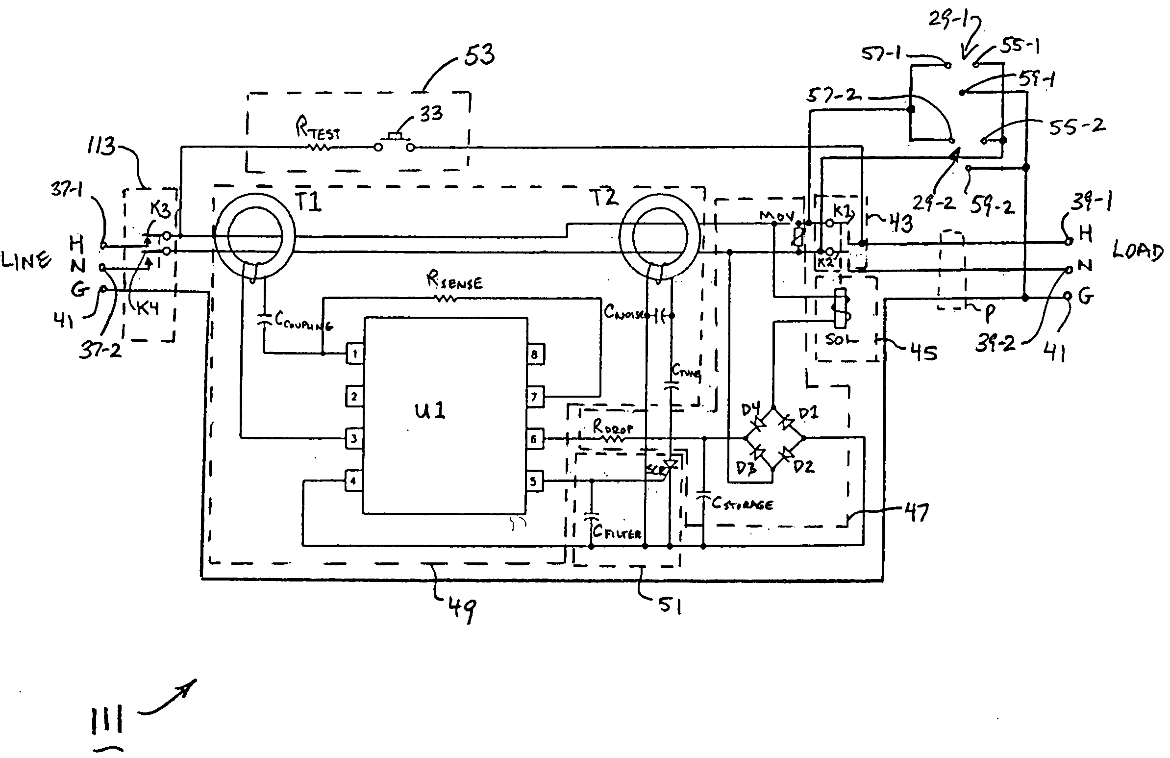
[0060] Accordingly, referring now to FIG. 4, there is shown a ground fault circuit interrupter (GFCI) which is constructed according to the teachings of the present invention, the GFCI being identified generally by reference numeral 111. As will be described further below, GFCI 111 differs from prior art GFCI 11 in that GFCI 111 provides ground fault protection to outlets 29 in two directions (i.e., in either direction between terminals 37 and 39) whereas prior art GFCI 11 provides ground fault protection to outlets 29 in only one direction (i.e., in the direction from terminals 37 to terminals 39).

[0061] GFCI 111 is identical in all respects with GFCI 11 with two notable distinctions.

[0062] As a first notable distinction of GFCI 111 in view of GFCI 11, it should be noted that GFCI 111 includes a second circuit breaker 113 for controlling the delivery of power along conductive lines H and N from the power source to the load. Circuit breaker 113 includes a pair of normally closed, s...

second embodiment

[0067] Referring now to FIG. 5, there is shown a ground fault circuit interrupter (GFCI) which is constructed according to the teachings of the present invention, the GFCI being identified generally by reference numeral 211. As will be described further below, GFCI 211 differs from prior art GFCI 11 in that GFCI 211 provides ground fault protection to outlets 29 in two directions (i.e., in either direction between terminals 37 and 39) whereas prior art GFCI 11 provides ground fault protection to outlets 29 in only one direction (i.e., in the direction from terminals 37 to terminals 39).

[0068] GFCI 211 is identical in all respects with GFCI 11 with two notable distinctions.

[0069] As a first notable distinction of GFCI 211 in view of GFCI 11, it should be noted that outlets 29 in GFCI 211 are connected to conductive lines H and N of the power cord at a location between circuit breaker 43 and line side terminals 37 (whereas outlets 29 in GFCI 11 are connected to conductive lines H and...

third embodiment

[0074] Referring now to FIG. 6, there is shown a ground fault circuit interrupter (GFCI) which is constructed according to the teachings of the present invention, the GFCI being identified generally by reference numeral 311. As can be appreciated, GFCI 311 operates in a similar manner as GFCI 211. As such, it is to be understood that GFCI 311 functions by (1) providing ground fault protection to outlets 29 when the power source and load are connected to GFCI 311 in a proper manner and (2) maintaining GFCI 311 in a tripped condition (i.e., suspending the application of power from the line to the load and outlets 29) when the power source and load are connected to GFCI 311 in the reverse order.

[0075] The sole distinction between GFCI 311 and GFCI 211 relates to the fact that GFCI 311 includes a reverse wiring circuit 313 which differs slightly in construction from reverse wiring circuit 213 in GFCI 211. Specifically, reverse wiring circuit 313 is similar to reverse wiring circuit 213 ...


PUM


Abstract

A ground fault circuit interrupter (GFCI) for use with a power cable which connects a power source to a load. The GFCI includes first and second pairs of terminals which are located at opposite ends of the power cable, the first pair of terminals being designated for connection with the power source and the second pair of terminals being designated for connection with the load. A pair of electrical outlets are connected to the power cable at a location between the first and second pairs of terminals. A first circuit breaker is located in the power cable between the pair of electrical outlets and the second pair of terminals. A ground fault detection circuit detects the presence of a ground fault condition in the power cable and, in turn, generates a trip signal which is used to energize a solenoid that is ganged to the first circuit breaker. In one embodiment, a second circuit breaker is located in the power cable between the first pair of terminals and the pair of electrical outlets, the second circuit breaker being ganged to the first circuit breaker. In this manner, the GFCI provides ground fault protection regardless of whether the power source is connected to the first or second pairs of terminals. In another embodiment, a reverse wiring circuit is provided which generates an artificial ground fault condition when the power source is improperly connected to the second pair of terminals rather than the first pair of terminals.

Description

CROSS-REFERENCE TO RELATED APPLICATIONS [0001] The present application claims the benefit under 35 U.S.C. 119(e) of U.S. provisional Patent Application Ser. No. 60 / 513,469, filed Oct. 22, 2003, the disclosure of which is incorporated herein by reference.BACKGROUND OF THE INVENTION [0002] The present invention relates generally to electrical safety devices and more particularly to ground fault circuit interrupters (GFCIs). [0003] Alternating current (AC) power is typically delivered from a power source (e.g., a power plant) to a load (e.g., an electrical appliance plugged into a conventional electrical outlet) through a network of interconnected power cables, each power cable comprising a pair of conducting lines. Specifically, each power cable typically comprises a hot line (which is also commonly referred to in the art as a hot wire or a power line) and a neutral line (which is also commonly referred to in the art as a neutral wire). [0004] The hot line is provided with a first end...

Claims


Application Information

Patent Timeline
IPC IPC(8): H02H3/33
CPCH02H3/338
Inventor AROMIN, VICTOR V.
Owner TOWER MFG
Why Eureka
Try Eureka