
Transbronchial needle aspiration device

a technology of transbronchial veins and needles, which is applied in the field of tissue sampling devices, can solve the problems of uncontrollable bleeding, death, and substantial complicating of the manipulation of the device, and achieves the effect of mass production and convenient operation

Active Publication Date: 2009-12-01
BOSTON SCI SCIMED INC
View PDF63 Cites 6 Cited by
  • Summary
  • Abstract
  • Description
  • Claims
  • Application Information

AI Technical Summary

Benefits of technology

The present invention provides a tissue sampling device for use in transbronchial needle aspiration that is easy to use, cost-effective, and can be mass-produced. The device includes a flexible catheter with a sampling needle and a wire for moving the needle between a first position and a second position. The device can be centered within the flexible catheter while still providing space for fluid flow. The device can be fixed to a handle assembly or a compressed spring. The technical effects of the invention include improved ease of use, reduced costs, and improved tissue sampling for transbronchial needle aspiration.

Problems solved by technology

One such shortcoming is the risk of uncontrollable bleeding if the biopsy needle, which may be quite large in diameter, pierces or shears a blood vessel.
Moreover, in extreme cases, the condition may be fatal.
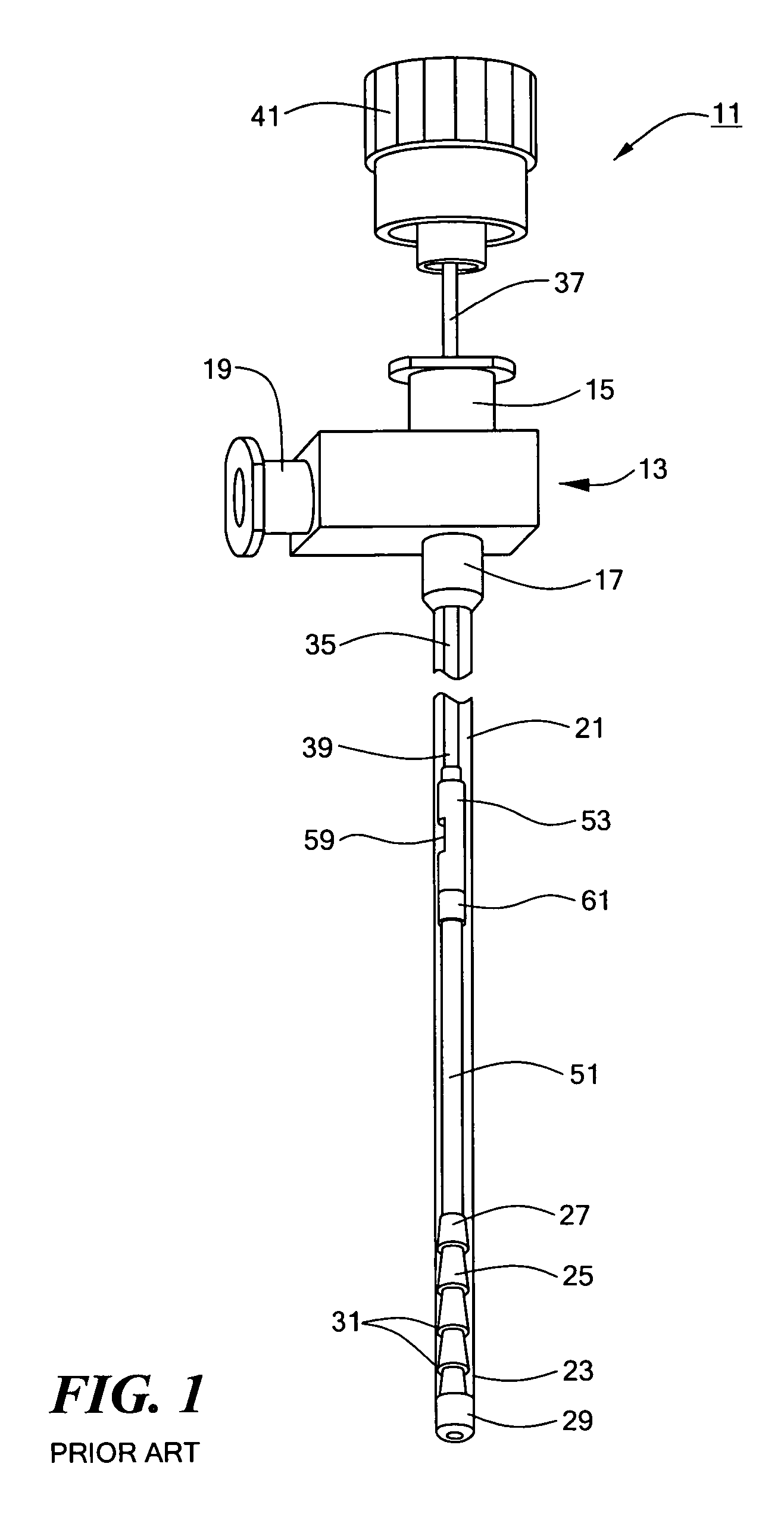
However, as can readily be appreciated, such a requirement substantially complicates the manipulation of device 11, especially by an individual operator.
More specifically, the present inventors have found that the perpendicular orientation of a syringe relative to the longitudinal axis of catheter 21 makes device 11 cumbersome and difficult to manipulate by an individual operator.
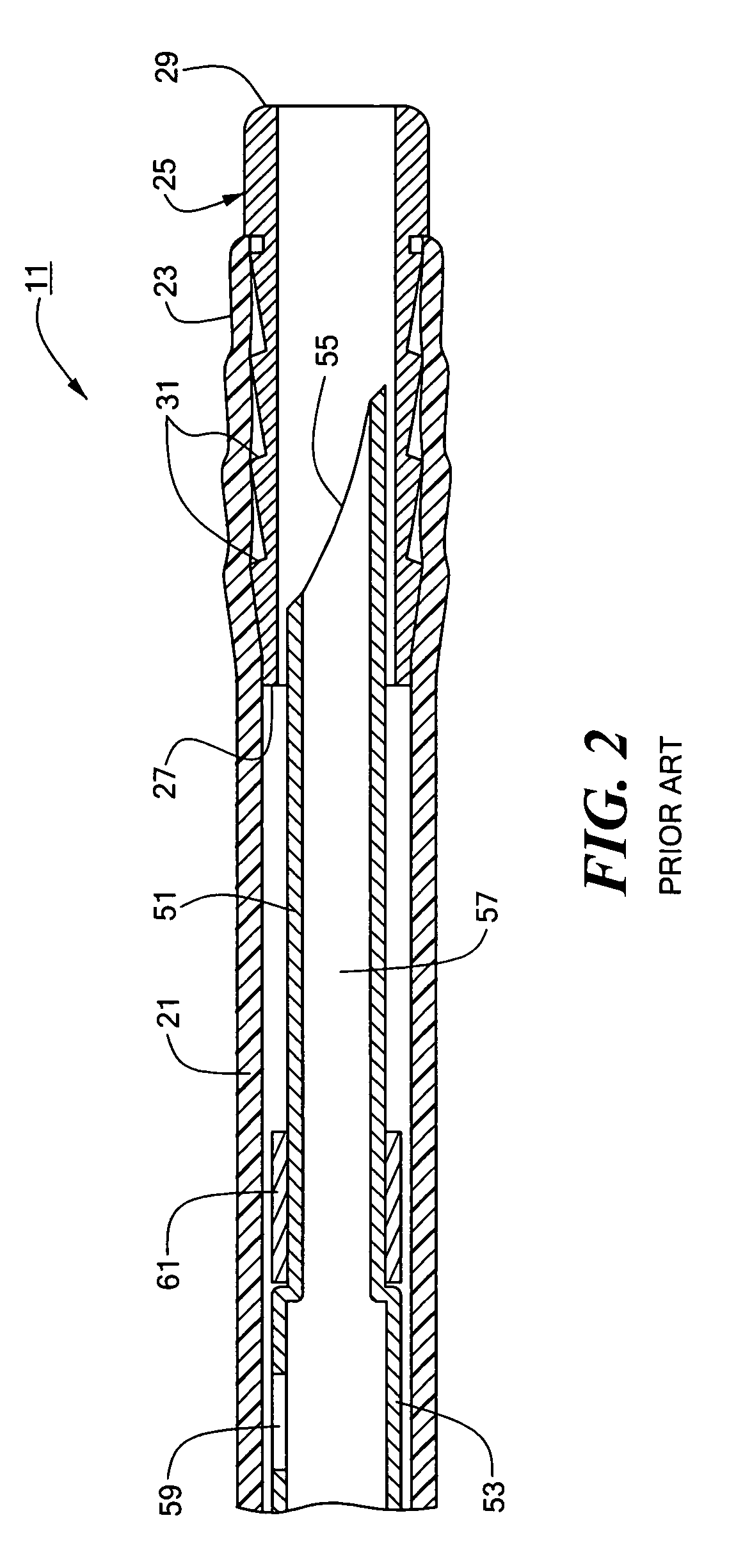
As can readily be appreciated, if needle 51 cannot be fully retracted when sampling is not being performed, damage may occur to equipment, operators and / or the patient.

Method used


Image

  • Transbronchial needle aspiration device
  • Transbronchial needle aspiration device
  • Transbronchial needle aspiration device

Examples


Embodiment Construction

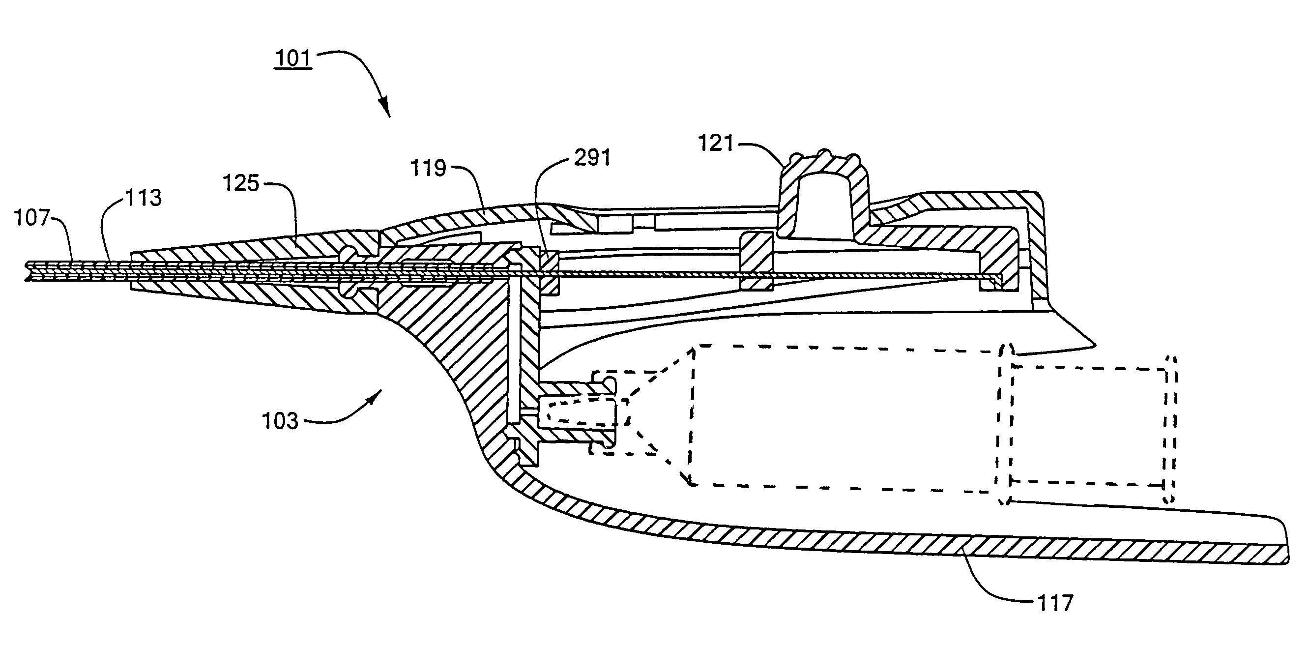
[0056]Referring now to FIGS. 3, 4, 5, 6(a) and 6(b), there are shown various views, respectively, of one embodiment of a transbronchial needle aspiration (TBNA) device constructed according to the teachings of the present invention, said TBNA device being represented generally by reference numeral 101.

[0057]Device 101 comprises a handle assembly 103, a wire 105, a flexible catheter 107, a sampling needle 109, a hub 111, a jacket 113 and a spring 115.

[0058]Handle assembly 103, in turn, comprises a body 117, a cover 119, a button slide 121, a syringe connector 123 and a strain relief member 125.

[0059]Referring now to FIGS. 7(a) through 7(f), body 117 is a unitary, generally C-shaped member, preferably made of a durable molded plastic or another similarly suitable material, comprising a top portion 131, a distal end portion 133 and a bottom portion 135, the sides and proximal end of body 117 being open. Top portion 131, distal end portion 133 and bottom portion 135 collectively define ...


PUM


Abstract

Transbronchial needle aspiration (TBNA) device. In one embodiment, the device comprises a handle and a flexible catheter, the handle having a bore, the proximal end of the catheter being fixed within the handle bore. A protective tubular hub having a flared distal end is press-fit coaxially within the distal end of the catheter, the distal end of the catheter being sealed around the distal end of the hub so as to define a distal opening. A hollow needle having a sharp tip at its distal end is disposed within the catheter, the needle tip being sized for insertion through the distal opening of the catheter. The distal end of a flexible wire is coupled to the proximal end of the needle, the proximal end of the wire extending through the handle bore and coupled to a button slide accessible through a slot in the handle. The button slide is movable between a distal position in which the needle tip extends through the distal opening of the catheter and a proximal position in which the needle tip is disposed within the hub. When in either its distal position or its proximal position, a pawl on the button slide releasably engages a corresponding notch on the handle to lock the button slide in place.

Description

BACKGROUND OF THE INVENTION[0001]The present invention relates generally to tissue sampling devices and relates more particularly to transbronchial needle aspiration devices.[0002]In order to diagnose and to stage lung cancer in a patient, it is often necessary to biopsy a tissue sample from a nearby lymph node of the patient. One type of technique that has been used in the past to obtain such a tissue sample involves percutaneously inserting a sampling needle through the patient's chest into the patient's lung and then through the bronchial wall of the lung into a nearby lymph node. Examples of devices adapted for percutaneous tissue sampling are disclosed in the following U.S. patents, all of which are incorporated herein by reference: U.S. Pat. No. 5,971,939, inventors DeSantis et al., which issued Oct. 26, 1999; U.S. Pat. No. 5,713,368, inventor Leigh, which issued Feb. 3, 1998; U.S. Pat. No. 4,799,494, inventor Wang, which issued Jan. 24, 1989; and U.S. Pat. No. 4,766,907, inve...

Claims


Application Information

Patent Timeline
Patent Type & Authority Patents(United States)
IPC IPC(8): A61B10/00A61B10/02A61B10/04
CPCA61B10/04A61B10/0283A61B2010/045
Inventor GRIGORYANTS, SERGEY S.MASEDA, LUIS J.
Owner BOSTON SCI SCIMED INC
Learn More