High performance reflector cooling system for projectors

a projector and reflector technology, applied in the field of high-performance compound reflector and cooling system, can solve the problems of reduced coupling efficiency, local distortion, and inability to normally be done, and achieve the effect of large diameter

Active Publication Date: 2005-06-02
CHRISTIE SA
View PDF8 Cites 6 Cited by
  • Summary
  • Abstract
  • Description
  • Claims
  • Application Information

AI Technical Summary

Benefits of technology

[0009] It is an aspect of the present invention to provide a specific ellipsoidal shape of reflector for accommodating a cooling system. The shape of the ellipsoidal reflector according to the present invention allows the spherical element to have a larger diameter at the interface between the ellipsoid and sphere. This provides a location for an air deflector in a shape similar to the back of the ellipsoid for channeling air over and outside of the ellipsoid and then along the inside of the sphere.

Problems solved by technology

However, this is not usually done because of size constraints.
This often results in areas of the reflector having high temperature gradients, resulting in local distortion and reduced coupling efficiency.
However, air flow over the opposite end is usually too low for cooling.
Nonetheless, ensuring cost effective and efficient cooling of the reflector for high power Xe lamps (i.e. greater than 1 KW) while optimizing light collection on the integrator rod, remains a difficult challenge to projector designers.

Method used


Image

  • High performance reflector cooling system for projectors
  • High performance reflector cooling system for projectors
  • High performance reflector cooling system for projectors

Examples


Embodiment Construction

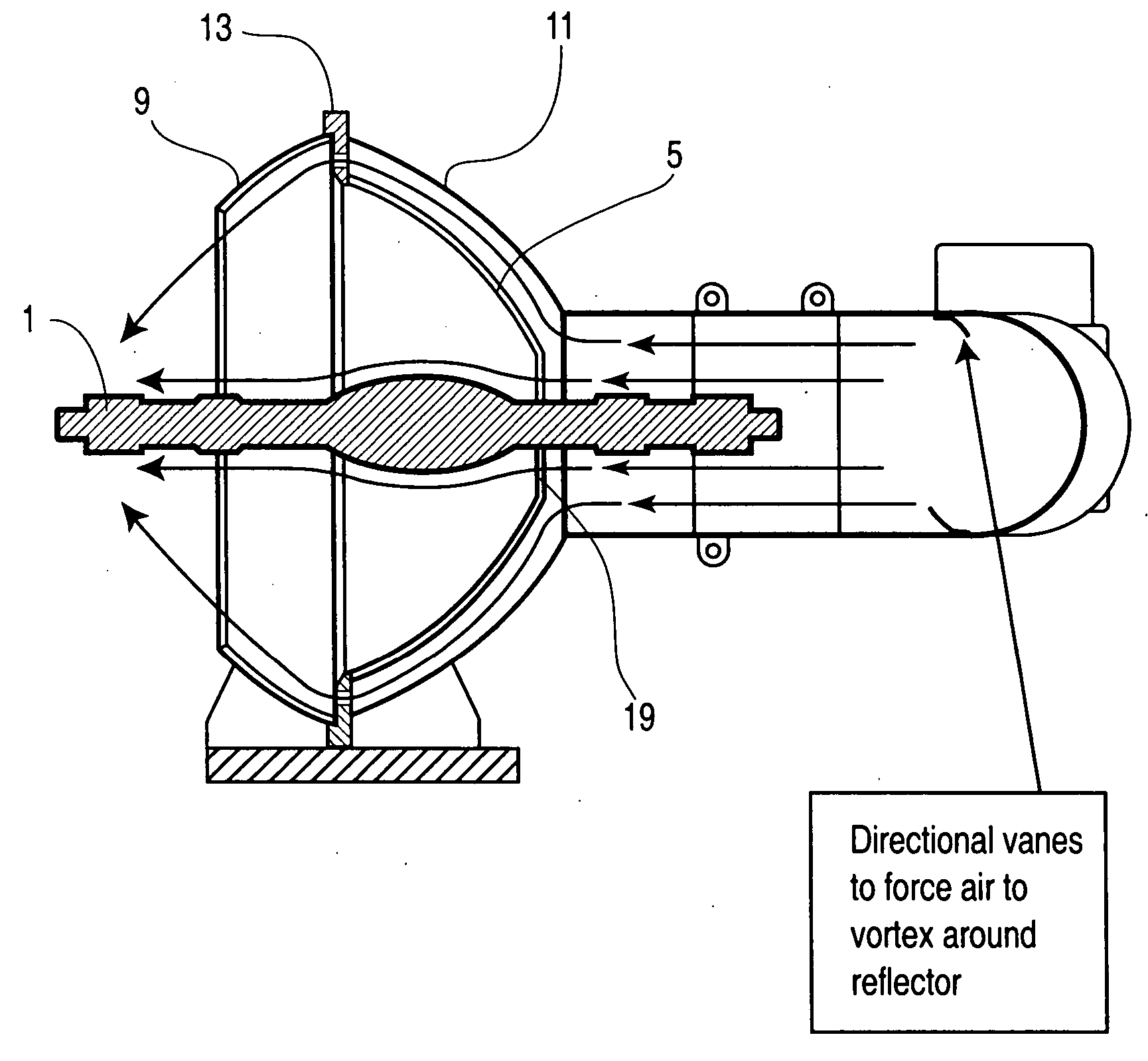
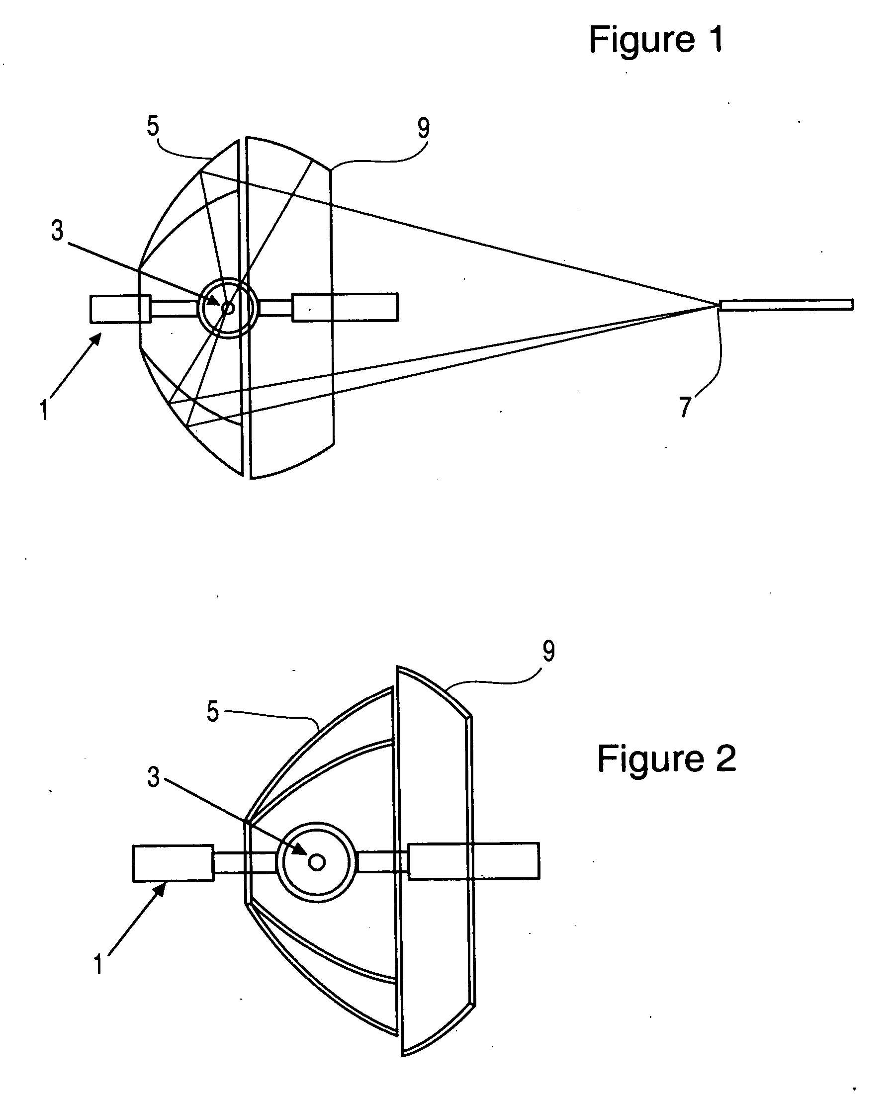
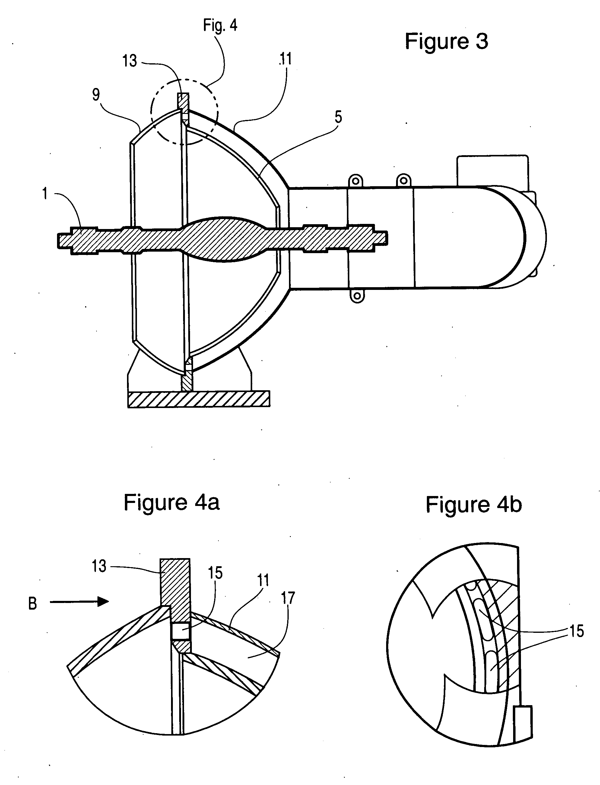
[0018]FIG. 1 shows the typical application of a compound lamp reflector. Light is generated by a lamp 1 having a bulb located at a first focal point 3 of ellipsoid reflector 5. Light is re-imaged at a second focal point 7 that is co-incident with an integrator rod. A secondary spherical reflector 9 provides retro-reflection of light from the first focal point 3 to allow the ellipsoidal reflector to be of compact design.

[0019] The layout of FIG. 1 shows rays reflecting off ellipsoid reflector 5 and retro reflecting off the sphere 9 to focal point 3 and then reflected to focal point 7. The location of the first focal point in relation to the vertex of the ellipsoid determines the location and power of lamp that can be used and thus limits the size of reflector. With a 6 kW lamp the focal point must be further from the vertex than for lower powered lamps, so that the lamp is further from the walls of the reflector thus increasing size. For the design of FIG. 1, the focal point is 103 ...


PUM


Abstract

A high performance compound reflector and cooling system for use with a projection system having a lamp for emitting light, an ellipsoid reflector for capturing said light from a first focal point of the ellipsoid reflector and focusing said light at a second focal point co-incident with an integrator rod, and a spherical reflector for retro-reflecting light through the first focal point for reflection by said ellipsoid retractor to said second focal point. The shape of the ellipsoid reflector according to the present invention allows the spherical element to have a larger diameter at the interface between the ellipsoid and sphere. This provides a location for an air deflector in a shape similar to the back of the ellipsoid for channeling air over and outside of the ellipsoid and than along tho inside of the sphere. The design of the reflector and air deflector allow cooling requirements to be substantially reduced.

Description

BACKGROUND OF THE INVENTION [0001] 1. Field of the Invention [0002] The present invention is directed to digital cinema projectors, and more particularly to a high performance compound reflector and cooling system for use with projection lamps such as Xenon (Xe) lamps. [0003] 2. Description of the Related Art [0004] High-end projectors that are capable of 8000 lumens and higher, typically use Xe bubble lamps coupled to an ellipsoidal reflector. The reflected light is captured from the first focal point of the reflector and is re-imaged at a second focal point. The second focal point is usually co-incident with an integrator rod or some other means of homogenizing the light. Illumination optics is then used to image the light from the integrator rod onto a light valves for projection. Typically, the ellipsoidal reflector contains a secondary spherical reflector. This allows the ellipsoidal reflector to be more compact, thereby reducing the size of the projector without sacrificing li...

Claims


Application Information

Patent Timeline
Patent Type & Authority Applications(United States)
IPC IPC(8): F21V29/02F21V29/505F21Y101/00G03B21/16
CPCG03B21/16
Inventor PINHO, GEORGE P.KOMARNYCKY, O. NICHOLASMATTHEWS, RICHARD
Owner CHRISTIE SA
Why Eureka
Try Eureka