High-sensitivity pickup actuator for disc drive

a pickup actuator and disc drive technology, applied in the direction of instruments, data recording, track finding/aligning, etc., can solve the problems of low efficiency and sensitivity of control in the tracking direction, higher etc., and achieve the effect of high control sensitivity, lower cost and complexity of manufactur

Inactive Publication Date: 2005-06-02
TS OPTICS CORP
View PDF4 Cites 8 Cited by
  • Summary
  • Abstract
  • Description
  • Claims
  • Application Information

AI Technical Summary

Benefits of technology

[0018] Accordingly, coils of a pickup actuator are arranged with respect to magnets having multiple regions with multiple polarities for high control sensitivity. In addition, such magnets are disposed at two sides of a bobbin for lower cost and complexity of manufacture.

Problems solved by technology

In the conventional optical pickup actuator of FIG. 1, one side of each tracking coil 7a or 7b forms an effective coil portion on which electromagnetic force in generated, resulting in low efficiency and sensitivity of control in the tracking direction T. Additionally in the conventional optical pickup actuator, magnets are disposed on all four sides of the bobbin 2 resulting in higher cost and complexity of manufacture.

Method used


Image

  • High-sensitivity pickup actuator for disc drive
  • High-sensitivity pickup actuator for disc drive
  • High-sensitivity pickup actuator for disc drive

Examples


first embodiment

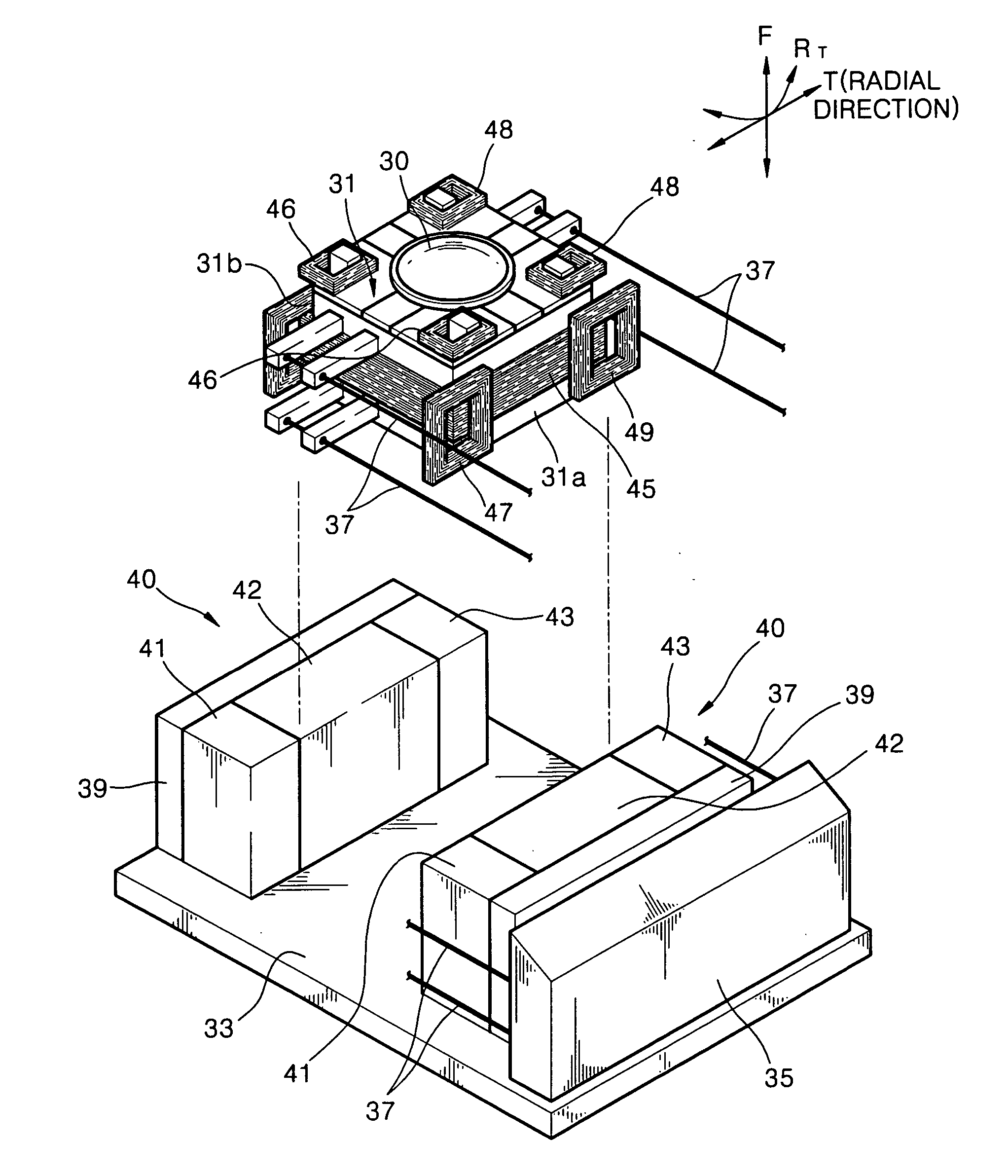
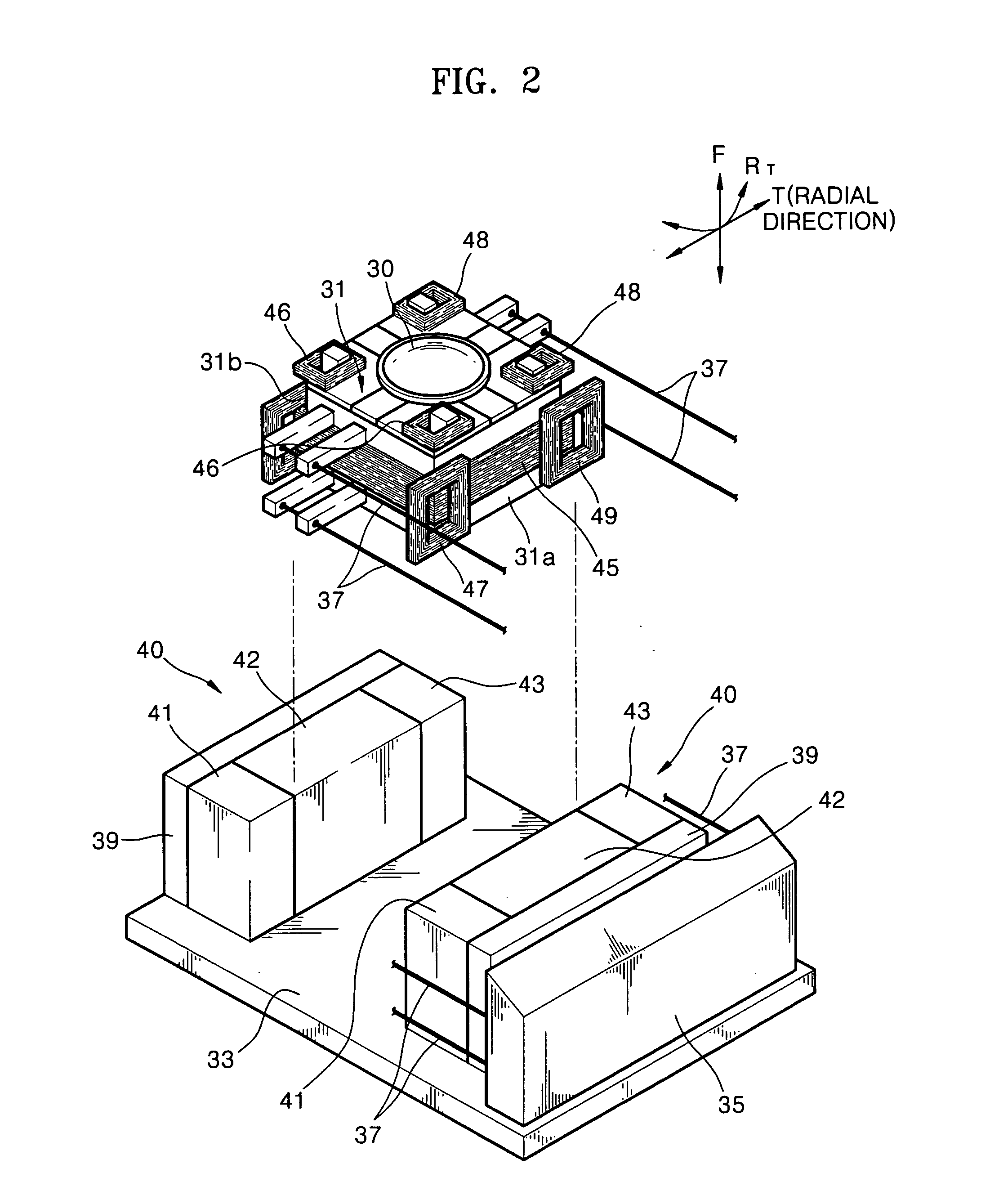
[0046] Referring to FIGS. 2, 3, 4, and 5, an optical pickup actuator of an optical disc drive according to the present invention includes a bobbin 31 having an objective lens 30 thereon. In addition, the optical pickup actuator includes a suspension 37 comprising four wires 37 that support the bobbin 31 while enabling the bobbin 31 to move with respect to a base 33. Each wire 37 has one end attached to the bobbin 31 and the other end attached to a holder 35 mounted on one side of the base 33.

[0047] Furthermore, the optical pickup actuator includes a magnetic circuit installed on the bobbin 31 and the base 33. The magnetic circuit includes a pair of magnets 40 that are disposed on the base 33 to face two sides 31a and 31b of the bobbin 31 that are parallel along a radial (i.e., tracking) direction of an optical disc. The magnetic circuit also includes a focus coil 45 wound around the bobbin 31. Furthermore, the magnetic circuit includes a plurality of tracking coils 47 and 49 mounted...

second embodiment

[0066]FIG. 6 is a perspective view of a magnetic circuit of an optical pickup actuator according to the present invention, and FIG. 7 is a side view of the magnetic circuit of FIG. 6. In this embodiment, the magnetic circuit includes a pair of magnets 140 disposed on the base 33 to face the two sides 31a and 31b of the bobbin 31 that are parallel along the radial direction of the optical disc. In addition, the magnetic circuit includes a focus coil 145 wound around the bobbin 31, a plurality of tracking coils 147 and 149 mounted on the two sides 31a and 31b of the bobbin 31 facing the magnets 140, and a tilt coil 146 wound around the bobbin 31 parallel to the focus coil 145.

[0067] The magnets 140 are mounted on the base 33 to face the two sides 31a and 31b of the bobbin 31 along the radial direction T of the optical disc. Each magnet 140 includes a middle region 142 and two side regions 141 and 143 having at least portions disposed parallel along the focus direction F. The sides reg...

third embodiment

[0080] In addition, the magnetic circuit of the third embodiment includes a focus coil 245 wound around the bobbin 31. Furthermore, the magnetic circuit includes a plurality of tracking coils 247 and 249 and a plurality of tilt coils 246 and 248 installed on each of the two sides 31a and 31b of the bobbin 31 facing the pair of magnets 140.

[0081] Each one of the magnets 240 is mounted on the base 33 to face a respective one of the two sides 31a and 31b of the bobbin 31 along the radial direction T of the optical disc. Each magnet 240 includes a middle region 242 and side regions 241 and 243 having at least portions disposed parallel to one another along the focus direction F. The upper portion of the side regions 241 and 243 are disposed at opposite sides of the middle region 242.

[0082] The middle region 242 has a first magnetic polarity, and the side regions 241 and 243 each have a second magnetic polarity opposite of the first magnetic polarity. Further referring to FIG. 11, a com...


PUM

PropertyMeasurementUnit
polarityaaaaaaaaaa
widthaaaaaaaaaa
areaaaaaaaaaaa

Abstract

A pickup actuator of a disc drive includes a pair of magnets, each facing a respective side of a bobbin and having a middle region with a first polarity and side regions with a second polarity opposite of the first polarity. The pickup actuator includes a plurality of tracking coils disposed on the respective sides of the bobbin facing the magnets. Each tracking coil has two effective coil portions with one facing the middle region and the other facing one of the side regions of the magnet, for higher sensitivity. The magnets are disposed at two sides of a bobbin for lower cost and complexity of manufacture.

Description

BACKGROUND OF THE INVENTION [0001] This application claims priority to Korean Patent Application No. 2003-0080100, filed on Nov. 13, 2003, in the Korean Intellectual Property Office, the disclosure of which is incorporated herein in its entirety by reference. [0002] 1. Field of the Invention [0003] The present invention relates generally to pickup actuators for disc drives such as optical pickup actuators, and more particularly to a pickup actuator having effective coil portions for high sensitivity. [0004] 2. Description of the Related Art [0005] An optical pickup records and / or reproduces information on / from an optical disc within an optical disc drive. The optical pickup moves in a radial direction over the optical disc that is an optical information storage medium during such recording / reproducing. [0006] A pickup actuator moves an objective lens of the optical pickup in tracking, focus, and / or tilt directions such that a light beam is focused on a desired spot of the optical di...

Claims


Application Information

Patent Timeline
Patent Type & Authority Applications(United States)
IPC IPC(8): G11B7/00G11B7/09G11B7/095G11B21/10
CPCG11B7/0933G11B7/0956G11B7/0935G11B7/09
Inventor SONG, BYUNG-YOUNKANG, HYUNG-JOOJANG, DAE-JONG
Owner TS OPTICS CORP
Why Eureka
Try Eureka