
Methods using a dual balloon telescoping guiding catheter

a guiding catheter and telescopic technology, applied in the field of guiding catheters, can solve the problems of time-consuming, expensive, unnecessary trauma to patients, and complicated end goal,

Inactive Publication Date: 2005-06-02
CARDIAC PACEMAKERS INC
View PDF36 Cites 110 Cited by
  • Summary
  • Abstract
  • Description
  • Claims
  • Application Information

AI Technical Summary

Benefits of technology

[0016] According to a further aspect, after engaging the destination vessel with the inner guide, the outer guide is distally advanced over the inner guide to engage the destination vessel with the outer guide. The annular balloon is inflated to occlude blood flow. A contrast media is injected into the guiding catheter for mapping blood vessels. Various types of sensing can be employed at the distal end of the guiding catheter to assist in locating a destination vessel or structure of interest.

Problems solved by technology

This endeavor, however, is complicated by the fact that the location of the coronary sinus ostium may vary appreciably from one patient to another, especially among patients with diseased hearts.
Replacing a catheter in this manner is time consuming, expensive, and can cause unnecessary trauma to the patient.
Even when the catheter has an ideal shape for a given application, the size and flexibility of the catheter that provides maneuverability through a convoluted access path becomes a disadvantage when trying to manipulate the distal end of the catheter in the right atrium.
Further, once the catheter has cannulated the destination vessel, the flexible distal tip may be dislodged from the destination vessel due to shape distortions caused by introducing a payload through the catheter.
Finding and cannulating the coronary sinus, for example, can become a time consuming, trial and error procedure even in a healthy patient.
Patients exhibiting symptoms of advanced heart disease can have blockages or deformations of heart structure, further complicating the task of locating the ostium of the coronary sinus.

Method used


Image

  • Methods using a dual balloon telescoping guiding catheter
  • Methods using a dual balloon telescoping guiding catheter
  • Methods using a dual balloon telescoping guiding catheter

Examples


Embodiment Construction

[0026] In the following description of the illustrated embodiments, references are made to the accompanying drawings which form a part hereof, and in which is shown by way of illustration, various embodiments in which the invention may be practiced. It is to be understood that other embodiments may be utilized, and structural and functional changes may be made without departing from the scope of the present invention.

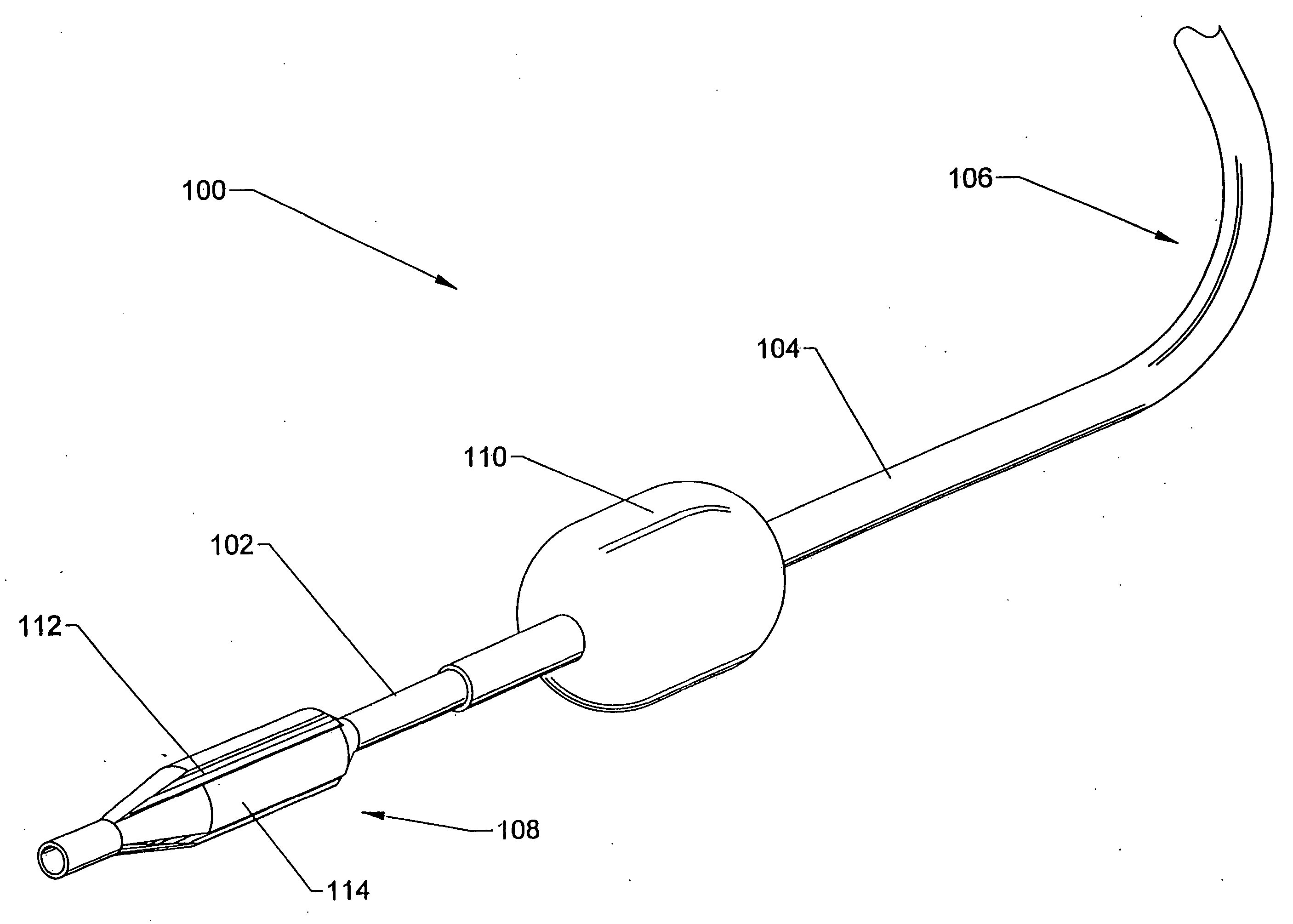
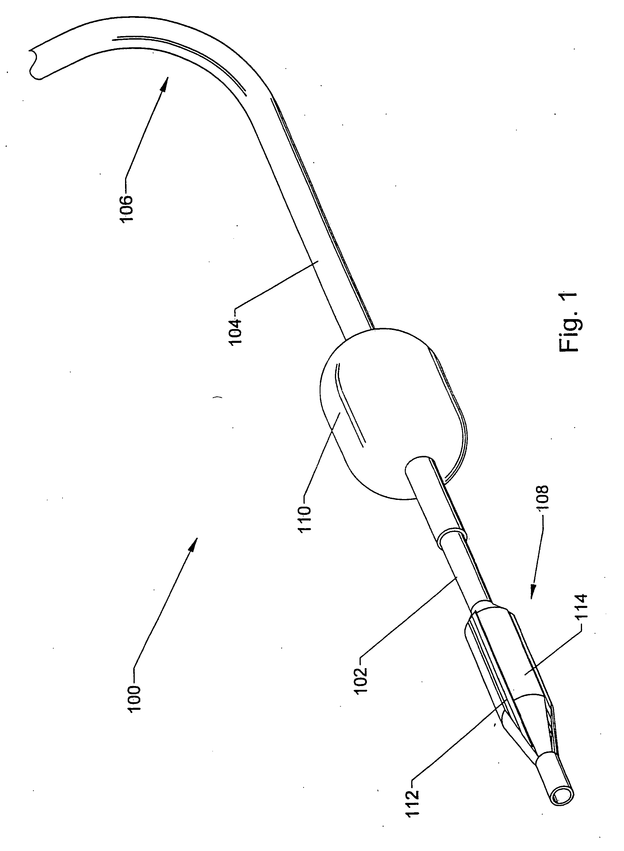
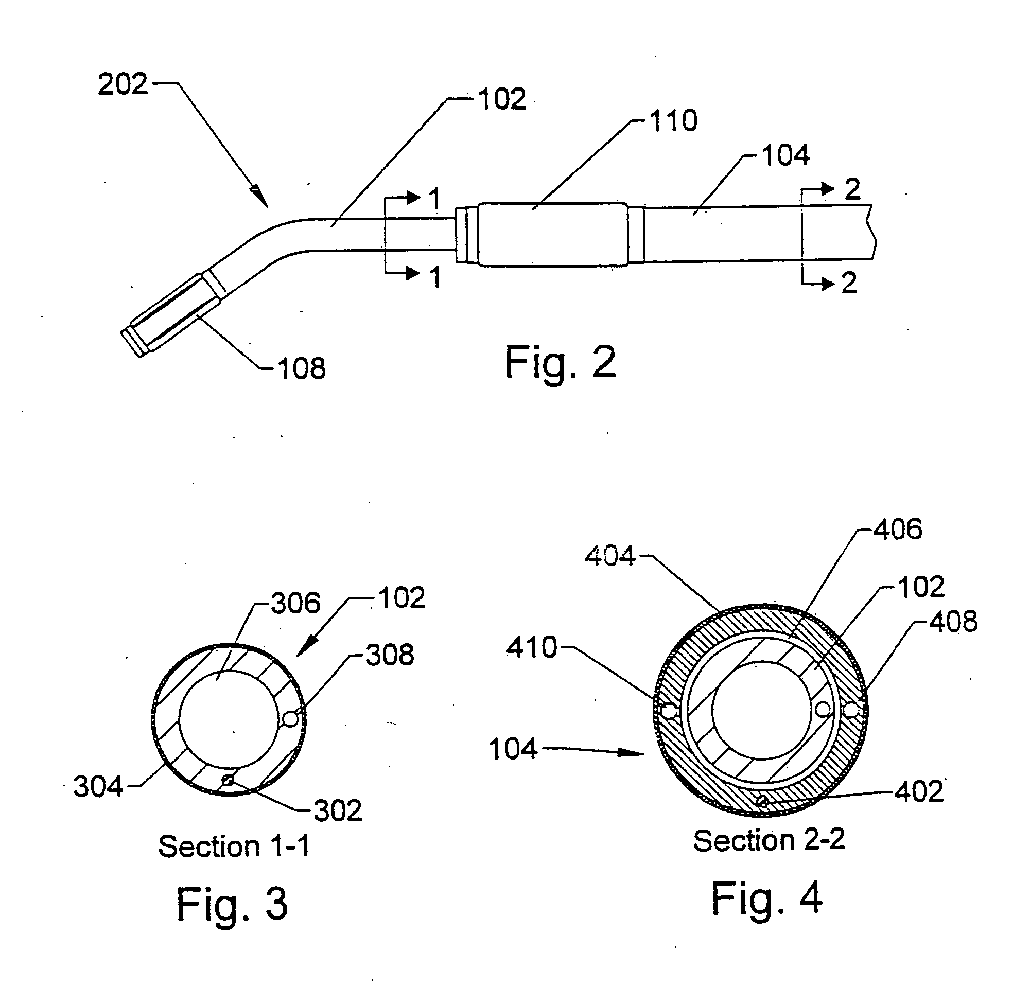
[0027] In FIG. 1, a catheter according to the present invention, generally indicated by reference numeral 100, is illustrated. The catheter 100 utilizes a telescoping guide configuration that includes an inner guide 102 movably disposed within an outer guide 104. The outer guide 104 has a pre-formed curve 106 near a distal end. The pre-formed curve 106 typically includes a shape optimized for the intended access path and destination vessel. Fluted and annular balloons 108, 110 are fixably mounted to the inner and outer guides 102, 104, respectively.

[0028] The fluted b...


PUM


Abstract

A guiding catheter comprises an outer guide having a guide lumen and an annular balloon mounted to a distal end of the outer guide, and an inner guide movably disposed within the guide lumen of the outer guide, the inner guide comprising a fluted balloon mounted to a distal end of the inner guide. A method involves selectably pressurizing and depressurizing the annular balloon to control occlusion of fluid flow relative to the annular balloon, and selectably pressurizing and depressurizing the fluted balloon independently of pressurizing and depressurizing the annular balloon to permit perfusion of fluid flow relative to the fluted balloon and control anchoring of the fluted balloon within a generally tubular structure.

Description

RELATED PATENT DOCUMENTS [0001] This is a divisional of U.S. patent application Ser. No. 10 / 132,093, filed on Apr. 25, 2002, to which Applicant claims priority under 35 U.S.C. §120, and which is incorporated herein by reference.FIELD OF THE INVENTION [0002] The invention relates generally to catheters and use of same, and more particularly to methods using guiding catheters having balloons affixed to the distal ends of telescoping inner and outer guides. BACKGROUND OF THE INVENTION [0003] Catheters are used in a variety of medical procedures. In some applications, these devices provide physicians the ability to explore, operate, and insert drugs / medical devices in various reaches of the anatomy without invasive surgery. Oftentimes, the catheters have medical devices mounted on the catheter shaft. For example, an electrophysiological (EP) ablation catheter has an ablation electrode mounted at a distal tip of the catheter. In another application, guiding catheters are used to create a...

Claims


Application Information

Patent Timeline
IPC IPC(8): A61F2/958
CPCA61M25/1011A61M2025/1086A61M2025/1015
Inventor CHOI, STEVEN B.
Owner CARDIAC PACEMAKERS INC
Learn More