Method and system for guiding a remote vehicle via lagged communication channel
What is Al technical title?
Al technical title is built by PatSnap Al team. It summarizes the technical point description of the patent document.
a technology of communication channel and remote vehicle, applied in the field of remote control of vehicles, can solve the problems of additional lagging, operator's inability to deal with up-to-date displayed images, and exhausting bandwidth resources
Active Publication Date: 2005-06-02
THE STATE OF ISRAEL MINIST OF AGRI & RURAL DEV AGRI RES ORG ARO VOLCANI CENT
View PDF15 Cites 50 Cited by
Summary
Abstract
Description
Claims
Application Information
AI Technical Summary
This helps you quickly interpret patents by identifying the three key elements:
Problems solved by technology
Method used
Benefits of technology
[0065] Preferably, the reference frame is reconstructed and displayed at the control center by either using said pixel representation data o...
Problems solved by technology
Transferring these bits via a fixed bit-rate channel requires buffering (at both ends of the channel), and thus results in additional lagging.
There may be other obstacles that contribute to the lag, for example, when the communication path is made via relay st...
Method used
Image
Click on the blue label to locate the original text in one second.
Reading with bidirectional positioning of images and text.
Examples
first embodiment
At the Vehicle
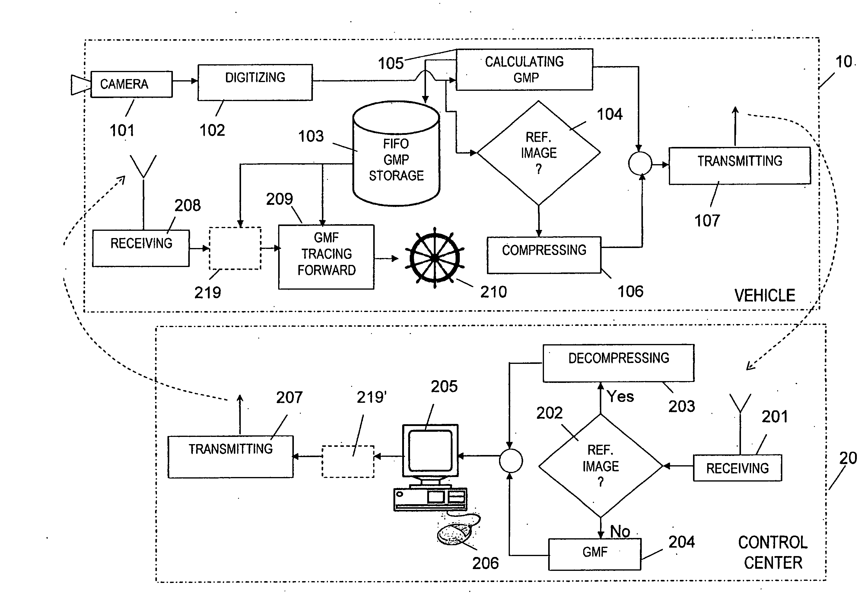
[0104] a. Each frame is marked by a “time stamp”, such as a unique sequential number. In this way, each frame can be identified both at the vehicle and at the control-center. In addition, some frames are designated as ‘reference’ frames and all the other frames are designated as ‘intermediate’ frames.
[0105] b. The global motion parameters for each frame (referenced to a previous ‘reference’ frame) are computed. These GMPs (and optionally the reference frames) are stored at the vehicle, along with their associated time stamps. Optionally, the full images with their associated time stamps may be stored at the vehicle.
[0106] c. Compressed reference frames, and calculated GMPs representing intermediate frames, each with its associated time stamp, are sequentially sent to the control center.
At the Control Center
[0107] d. The frames are displayed to the operator. Reference frames are first decompressed and then displayed, and intermediate frames are reconstructed using ...
second embodiment
At the Vehicle
[0113] a. Each frame is marked by a “time stamp”, such as a unique sequential number. In this way, each frame can be identified both at the vehicle and at the control-center. In addition, some frames are designated as ‘reference’ frames and all the other frames are designated as ‘intermediate’ frames.
[0114] b. The global motion parameters for each frame (referenced to a previous ‘reference’ frame) are computed. These GMPs (and optionally the reference frames) are stored at the vehicle, along with their associated time stamps.
[0115] c. Compressed reference frames, and calculated GMPs representing intermediate frames, each with its associated time stamp, are sequentially sent to the control center.
At the Control Center
[0116] d. The frames are displayed to the operator. Reference frames are first decompressed and then displayed, and intermediate frames are reconstructed using a GMF, given the corresponding GMPs of each intermediate frame and a corresponding previous ...
PUM
Abstract
The invention relates to a method for guiding from a remote control center a vehicle towards a target object, said remote control center communicating with the vehicle by means of a lagged communication channel, comprising: At the vehicle: (a) Periodically capturing frame images by a camera, assigning to each of said captured frames an associated unique time stamp, and saving within a storage at the vehicle full frame data or partial frame data of captured frames and their associated time stamps; (b) For a plurality of saved frames, sending to the control center via the lagged communication channel full frame data, partial frame data or a combination thereof with the corresponding associated time stamp for each sent frame so that approximate or exact version of the sent frames can be reconstructed and displayed at the control center; At the control center: (c) Receiving said frame data and associated time stamps, sequentially reconstructing frame images from each said sent full and/or partial frame data, and displaying the reconstructed images on a display; (d) Upon marking by an operator at the control center a point on a specific displayed frame, sending coordinates indication relating to said marked point as appearing on said specific frame or on a reference frame available at the control center, and the time stamp associated with said specific or reference frame, as is the case, to the vehicle; At the vehicle: (e) Receiving said coordinates indication as marked and the sent frame time stamp; (f) Given the coordinates indication and frame time stamp as received, fast forward tracing said point or object coordinates from the said frame towards the most recently available captured frame, thereby finding the coordinates of the same point or object as appearing in the most recently available captured frame; and (g) Providing the coordinates of the target point or object within the most recently available captured frame, as found, to an inner guidance sub-system of the vehicle, for enabling it to track said object.
Description
FIELD OF THE INVENTION [0001] The present invention relates to the field of remotely controlling a vehicle with the aid of imaging means. More particularly, the present invention is directed to a method and system for guiding a vehicle under lagged communication channel. BACKGROUND OF THE INVENTION [0002] In order to facilitate the reading of the description to follow, a number of terms and acronyms are defined below: [0003] The term “camera” refers herein to a device, system or facility that captures a 3D reality / object and transforms it to a series of images. Nowadays producing images from a 3D object can be carried out by a variety of means, such as a radar signal, an infrared camera or a video camera. The images are referred to herein as “frames”. [0004] The term “vehicle” refers herein to any type of object that is guided by an inner guidance sub-system. Examples for such vehicles: a car, aircraft, satellite, torpedo, missile, ship, etc. [0005] The term “automatic guiding syste...
Claims
Application Information
Patent Timeline
Application Date:The date an application was filed.
Publication Date:The date a patent or application was officially published.
First Publication Date:The earliest publication date of a patent with the same application number.
Issue Date:Publication date of the patent grant document.
PCT Entry Date:The Entry date of PCT National Phase.
Estimated Expiry Date:The statutory expiry date of a patent right according to the Patent Law, and it is the longest term of protection that the patent right can achieve without the termination of the patent right due to other reasons(Term extension factor has been taken into account ).
Invalid Date:Actual expiry date is based on effective date or publication date of legal transaction data of invalid patent.