
Calibration method of time measurement apparatus

a time measurement and time measurement technology, applied in the direction of instruments, horology, code conversion, etc., can solve the problems of limiting the operation speed of the counter, limiting measurement accuracy, and not realizing sufficient measurement accuracy

Active Publication Date: 2005-06-02
ADVANTEST CORP
View PDF4 Cites 23 Cited by
  • Summary
  • Abstract
  • Description
  • Claims
  • Application Information

AI Technical Summary

Problems solved by technology

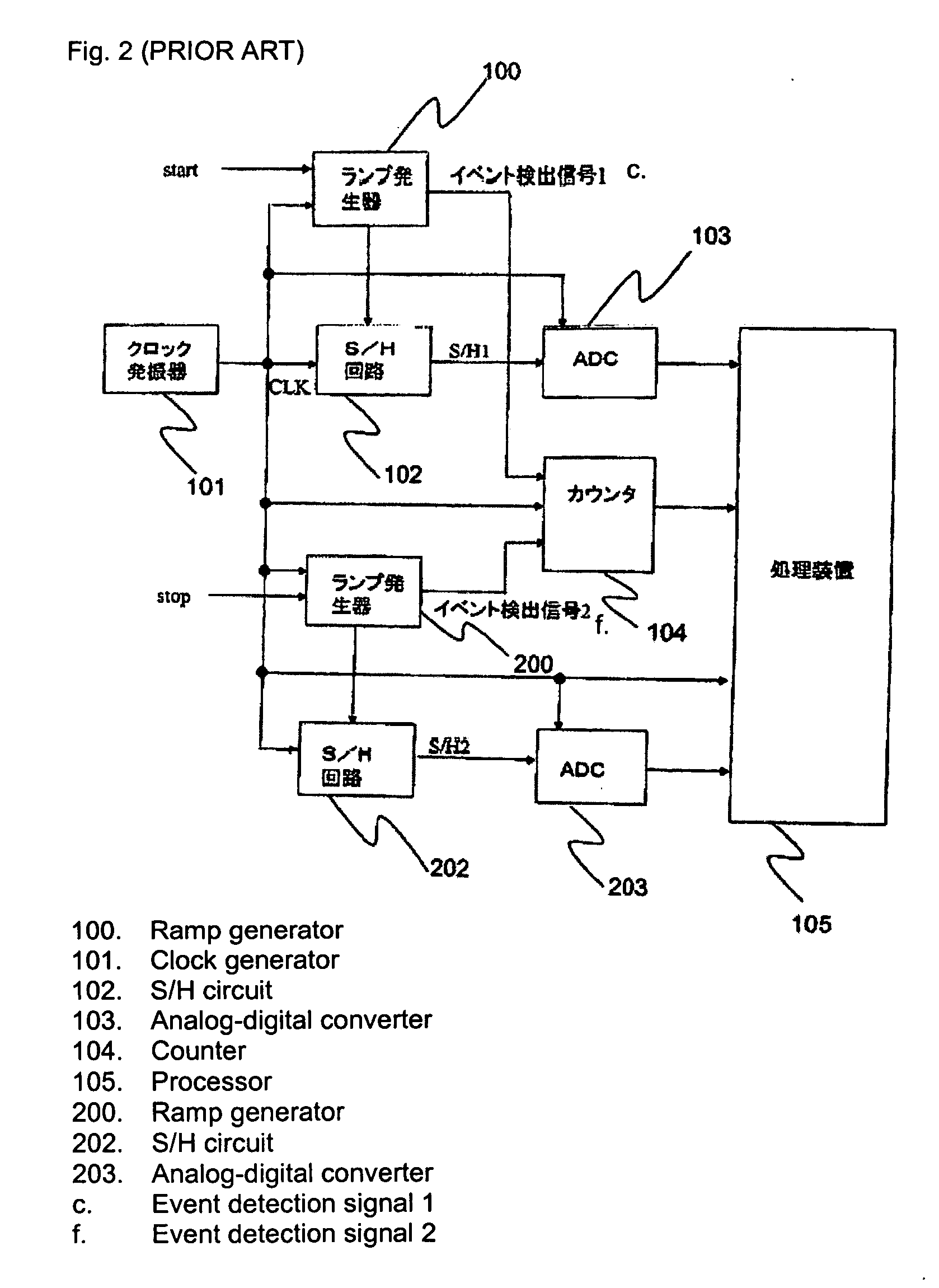
However, this measurement method cannot measure time intervals that are shorter than the clock period; therefore, although clock signals of a short period are necessary for obtaining good measurement accuracy, there are limits to the operating speed of the counter and this in turn limits measurement accuracy.
However, there is a problem in that sufficient measurement accuracy is not actually realized because a high-speed time-voltage converter or an ADC having good linear conversion properties does not exist.
However, it takes a very long time to determine the calibration value even when there are enough samples to improve accuracy.
Moreover, there is no method for generating completely random numbers.
Therefore, there is a problem in that measurement accuracy cannot be guaranteed.

Method used


Image

  • Calibration method of time measurement apparatus
  • Calibration method of time measurement apparatus
  • Calibration method of time measurement apparatus

Examples


Embodiment Construction

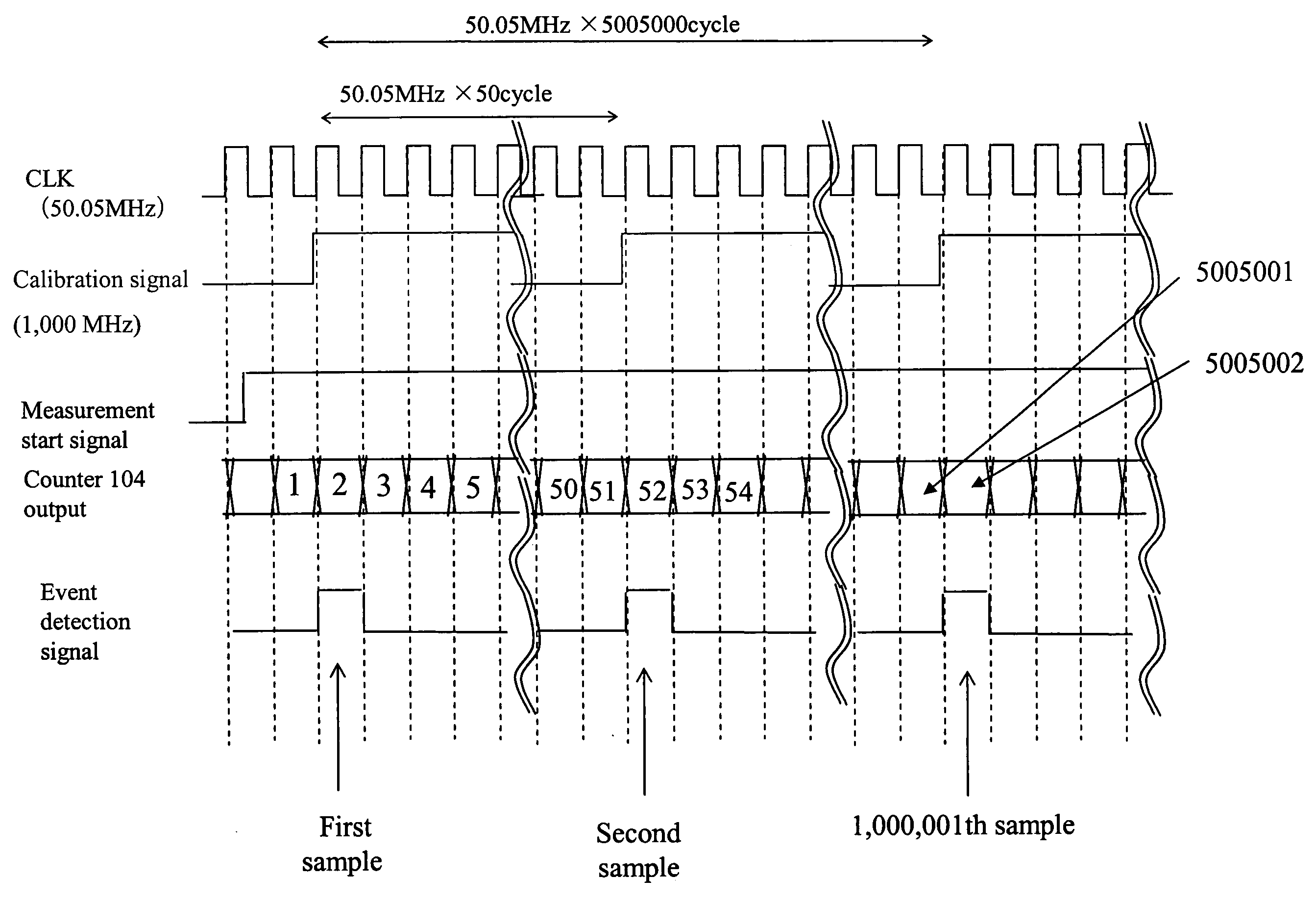
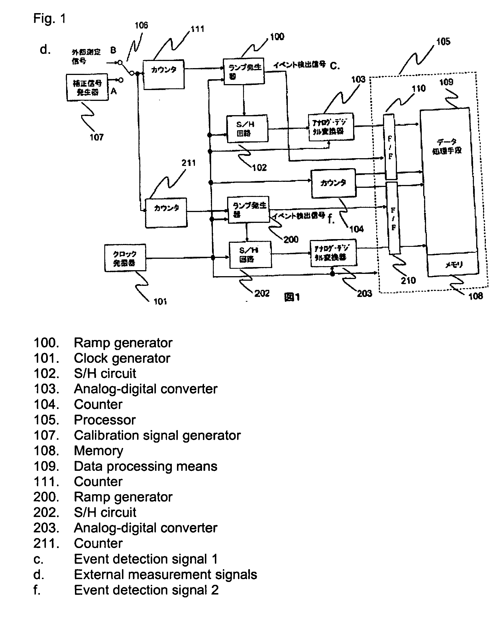
[0031] A calibration method for a time measurement apparatus that has time-voltage converter for converting the time interval of measurement signals and clock signals to voltage, analog-digital converter for converting this voltage to digital values, and time-interval measurement unit for measuring this time interval from these digital values, wherein it comprises a calibration signal generation step for calibrating the calibration signals for the subperiod of these clock signals, with these calibration signals having a shorter period difference than the time corresponding to the resolution of this analog-digital converter; a frequency distribution analysis step for repeatedly measuring these calibration signals, finding these digital values, and analyzing the cumulative frequency distribution of these digital values; and a calibration determining step for determining the calibration value for these digital values such that this cumulative frequency distribution is linear.

[0032] Th...


PUM


Abstract

A calibration method for a time measurement apparatus having time-voltage converter for converting the time interval of measurement signals and clock signals to voltage, analog-digital converter for converting this voltage to digital values, and time interval measurement device for measuring this time interval from these digital values, wherein it comprises a calibration signal generation step for calibrating the calibration signals for the subperiod of these clock signals, with these calibration signals having a shorter period difference than the time which corresponds to the resolution of this analog-digital converter; a frequency distribution analysis step for repeatedly measuring these calibration signals, finding this digital value, and analyzing the cumulative frequency distribution of these digital values; and a calibration determining step for determining the calibration value of these digital values such that this cumulative frequency distribution is linear.

Description

FIELD OF THE INVENTION [0001] The present invention relates to a calibration method for a time measurement apparatus, and in particular, to a calibration method for a time measurement apparatus whereby the time interval between signals is measured by converting the time interval between measurement signals and clock signals to a voltage difference and analog-digital conversion of this voltage difference. [0002] Discussion of the Background Art [0003] A time measurement apparatus for accurately measuring the time interval between signals has become necessary as a result of the increase in the speed of digital communications in recent years. The signal interval is generally found by counting the clocks generated between signal inputs and adding the clock period to the number of counts. However, this measurement method cannot measure time intervals that are shorter than the clock period; therefore, although clock signals of a short period are necessary for obtaining good measurement ac...

Claims


Application Information

Patent Timeline
IPC IPC(8): G01S1/24G04F10/04G04F10/10H03M1/10H03M1/50
CPCG04F10/10G04F10/04
Inventor MORI, YASUO
Owner ADVANTEST CORP
Learn More