Control system

a control system and control system technology, applied in the field of control systems, can solve the problems of deteriorating control accuracy, out of the allowable range of control variable y, unstable feedback loop, etc., and achieve the effect of accurate and stably controlled

Inactive Publication Date: 2005-06-02
HONDA MOTOR CO LTD
View PDF6 Cites 14 Cited by
  • Summary
  • Abstract
  • Description
  • Claims
  • Application Information

AI Technical Summary

Benefits of technology

[0036] According to the present invention, even if there is a phase lag of the control variable y relative to the manipulation variable x in a controlled object, the phase lag can be compensated. Hence, the control variable y can be accurately and stably controlled on the basis of the manipulation variable x according to the final desired value y2.

Problems solved by technology

If, however, a gain coefficient K (refer to expression (b)) in the integrating unit A3 is high, then the feedback loop becomes unstable and oscillates or vibrates; therefore, the gain coefficient K must be controlled low.
As a result, an error (inaccuracy) of the control variable y relative to the desired value y0 increases, and control accuracy may deteriorate and the control variable y may be out of the allowable range.

Method used


Image

  • Control system
  • Control system
  • Control system

Examples


first embodiment

[0050] First, a control system according to the present invention will be explained in conjunction with FIG. 1 through FIG. 7.

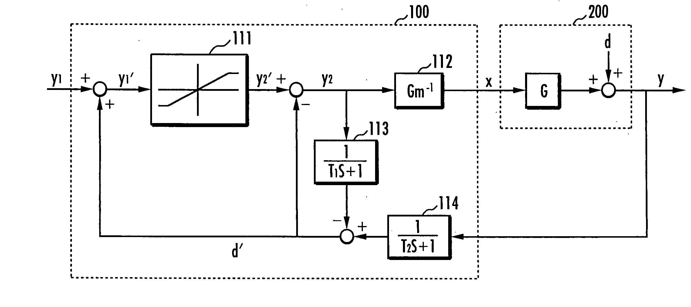
[0051] A control system 100 according to a first embodiment shown in FIG. 1 is equipped with a limiter 111, an inverse model arithmetic unit 112, a first filter 113, and a second filter 114. The control system 100 controls a control variable y of a controlled object 200 on the basis of a manipulation variable x.

[0052] The limiter 111 constitutes a “secondary estimating means” and determines and outputs a secondary estimation value y2′ according to an input primary estimation value y1′ on the basis of a mapping function (refer to FIG. 7(a)) represented by an expression (1) given below:

y2′=y1′ (if y−≦y1′≦y+)

y+ (if y+1′)

y− (if y1′−)  (1)

[0053] More specifically, if the primary estimation value y1′ is within an allowable range [y−, y+], then the limiter 111 determines the secondary estimation value y2′ that agrees with the primary estimation value y1′. If th...

second embodiment

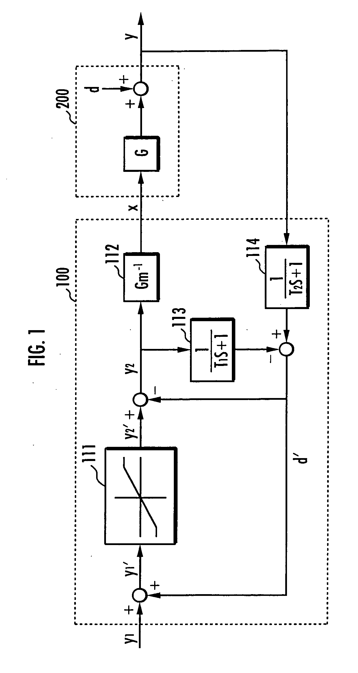
[0080] Referring now to FIG. 2, a control system according to the present invention will be explained.

[0081] A block diagram of a control system 100 according to the second embodiment shown in FIG. 2 is an equivalent modification of the block diagram of the control system 100 according to the first embodiment shown in FIG. 1, and can be approximated to T1 s to 0 in the low frequency range. Hence, the block diagram of the control system 100 according to the second embodiment can be obtained by going through approximate modifications to (primary lead filter of a time constant T1)*(limiter) before and after (limiter)*(primary lead filter of time constant T1 (transmission element T1 s+1)).

[0082] From the relationship Gm−1·G≦1 of expression (2), the inverse model arithmetic unit 112 in the control system 100 according to the first embodiment is omitted, and the transmission element of a controlled object 200 is set to 1.

[0083] The control system 100 according to the second embodiment s...

third embodiment

[0099] Referring now to FIG. 3, a control system according to the present invention will be explained.

[0100] A block diagram of a control system 100 according to the third embodiment shown in FIG. 3 is obtained by assuming that the time constants T1 and T2 of the first filter 113 and the second filter 114 share the same time constant T as that in the control system 100 according to the first embodiment shown in FIG. 1, and combining the two filters 113 and 114 into one filter.

[0101] The control system 100 according to the third embodiment is equipped with a limiter 131, an inverse model arithmetic unit 132, and a filter 133.

[0102] The limiter 131 and the inverse model arithmetic unit 132 share the same constructions as those of the limiter 111 and the inverse model arithmetic unit 112 in the control system 100 according to the first embodiment. The filter 133 is a primary lag filter of time constant T.

[0103] The control system 100 according to the third embodiment determines the ...


PUM


Abstract

A control system that constantly and accurately controls a control variable so that it remains within an allowable range is provided. The control system in accordance with the present invention estimates a steady-state deviation d in a controlled object as a steady-state deviation estimation value d′ on the basis of a control variable y and a final desired value y2. A control variable y in a controlled object based on the initial desired value y1 is estimated as the primary estimation value y1′ on the basis of at least the initial desired value y1 and the steady-state deviation estimation value d′. If a primary estimation value y1′ is within an allowable range, then a final desired value y2 agreeing with an initial desired value y1 is determined, while, if the primary estimation value y1′ is out of the allowable range, then the final desired value y2 is determined on the basis of at least a boundary value of the allowable range. A manipulation variable x is determined on the basis of the final desired value y2.

Description

TECHNICAL FIELD [0001] The present invention relates to a system for controlling a control variable of a controlled object. BACKGROUND ART [0002] Hitherto, as a control system having a limiting function, a control system A shown in FIG. 12 has been known. An output (control variable) y of a controlled object B is controlled by the control system A. [0003] The control system A is equipped with a manipulation variable determining unit A1, a limiter A2, and an integrating unit A3. [0004] The manipulation variable determining unit A1 has a transmission element G0 and outputs a primary manipulation variable x1 according to an expression (a) shown below on the basis of a difference y0−y between a desired value y0 and the control variable y. x1=G0·(y0−y)  (a) [0005] The limiter A2 outputs a secondary manipulation variable x2 on the basis of an input of the primary manipulation variable x1. To be more specific, the limiter A2 directly outputs the primary manipulation variable x1 as the seco...

Claims


Application Information

Patent Timeline
Patent Type & Authority Applications(United States)
IPC IPC(8): G05B11/36G05B13/02G05B13/04
CPCG05B11/36G05B13/041G05B13/021
Inventor TAKENAKA, TORU
Owner HONDA MOTOR CO LTD
Why Eureka
Try Eureka