
Large-scale seven-shaft linkage numerical control laying and winding integrated forming equipment

An equipment and seven-axis technology, applied in the field of laying and forming equipment and composite fiber mesh tapes, which can solve the problem that the supporting technology mold design technology cannot be carried out, the automatic tow laying technology cannot be systematically researched, and the engineering application of forming technology Difficulty and other problems, to achieve the effect of improving material utilization, stability and consistency, and improving efficiency

Inactive Publication Date: 2019-04-02
HUAZHONG UNIV OF SCI & TECH +4
View PDF0 Cites 8 Cited by
  • Summary
  • Abstract
  • Description
  • Claims
  • Application Information

AI Technical Summary

Problems solved by technology

However, the automatic tow equipment, process technology and corresponding prepreg tow preparation technologies have not been systematically studied, which brings great difficulties to the engineering application of this molding technology
At present, since domestic automatic tow laying equipment that can meet engineering applications has not been developed, there is a lack of necessary tow laying equipment as a research platform in China, which in turn leads to necessary supporting technologies such as tow prepreg technology, The research on laying process and mold design technology cannot be carried out, and it is impossible to conduct in-depth research on the automatic tow laying technology system

Method used

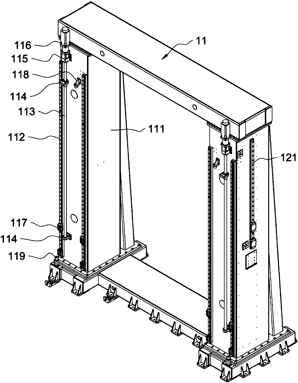
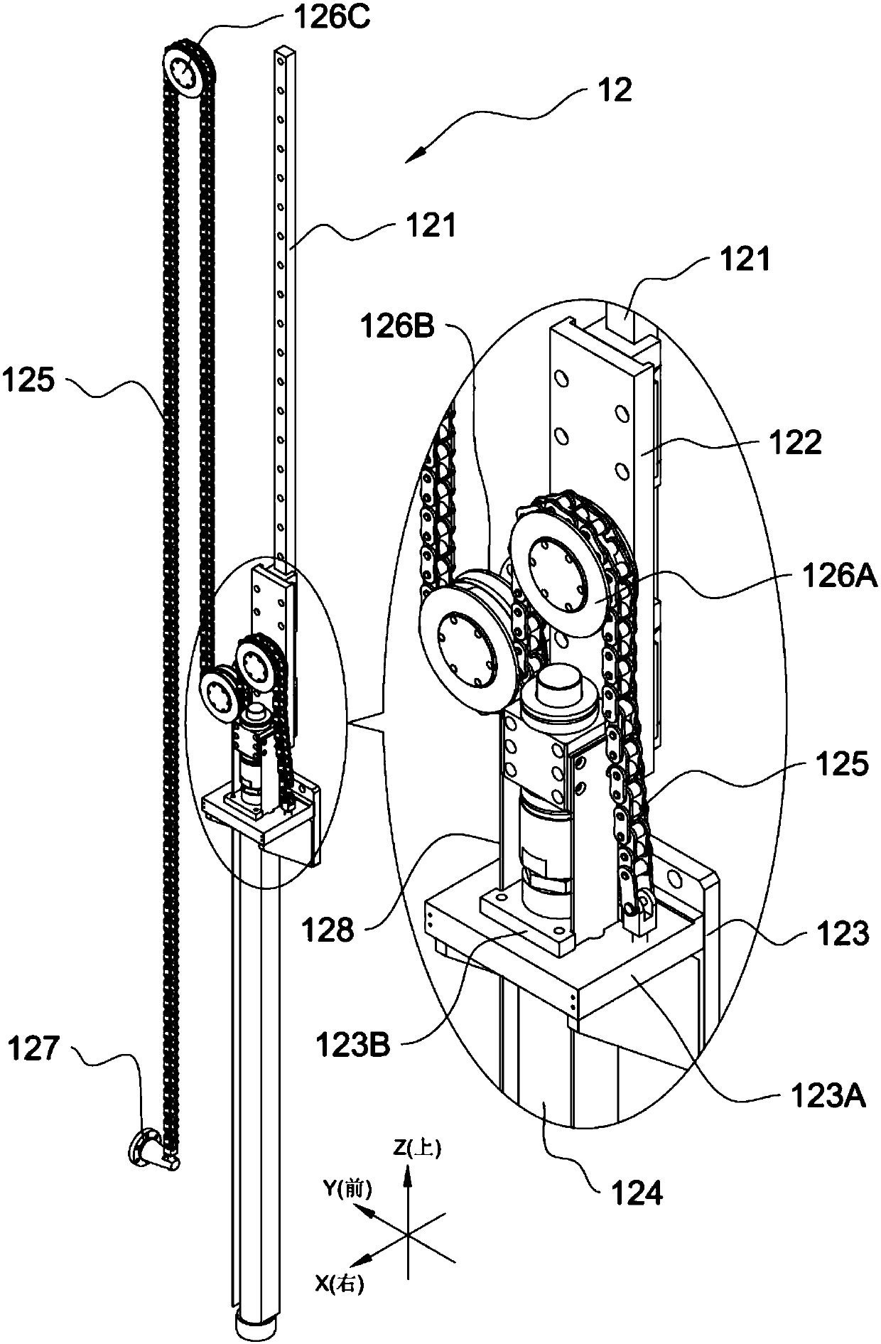

Image

  • Large-scale seven-shaft linkage numerical control laying and winding integrated forming equipment
  • Large-scale seven-shaft linkage numerical control laying and winding integrated forming equipment
  • Large-scale seven-shaft linkage numerical control laying and winding integrated forming equipment

Examples


Embodiment Construction

[0055] In order to make the object, technical solution and advantages of the present invention clearer, the present invention will be further described in detail below in conjunction with the accompanying drawings and embodiments. It should be understood that the specific embodiments described here are only used to explain the present invention, not to limit the present invention. In addition, the technical features involved in the various embodiments of the present invention described below can be combined with each other as long as they do not constitute a conflict with each other.

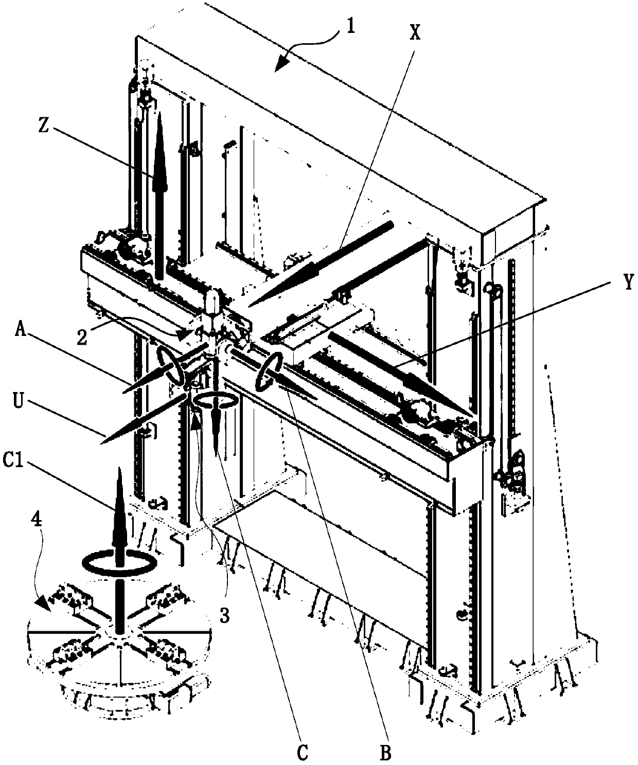
[0056] In order to achieve the above purpose, according to one aspect of the present invention, a large-scale seven-axis linkage numerical control laying and wrapping integrated forming equipment is provided, such as figure 1 As shown, the equipment includes: an equipment host 1, a wrapping wrist 2, a wrapping head 3, a rotary table 4 and a numerical control unit (not shown).

[0057] The equip...


PUM


Abstract

The invention belongs to the field of machine design and manufacturing-high grade numerical control machine tool and basic manufacturing equipment, and relates to large-scale seven-shaft linkage numerical control laying and winding integrated forming equipment. A main machine which is formed by three linear shafts and one rotating working table rotating shaft, and a laying and winding head which is driven by three rotating shafts are adopted to composite three translation movement and four rotation movement to achieve laying and winding head spatial motion track control and workpiece rotation.A conveying belt u shaft is adopted to drive winding and rewinding of a cloth belt and speed adjustment to achieve eight-shaft control seven-shaft linkage laying, and therefore automatic forming of acomposite material skin structure with all kinds of spacial special-shaped hook surfaces is achieved. The spatial motion track of the laying winding head can be directly controlled, even a workpiecewith the special-shaped hook surface can be accurately attached to the surface of the laying winding head for laying and winding, and therefore forming operation of material cutting after solidifyingand forming can be reduced and even avoided. Pollution is reduced, the cost is saved, and efficiency is improved. The automatic tow placing technology provides an equipment platform suitable for engineering application research and manufacture.

Description

technical field [0001] The invention belongs to the field of mechanical design and manufacturing-high-end numerical control machine tools and basic manufacturing equipment, and relates to a large double-column vertical eight-axis control seven-axis linkage numerical control tape winding / laying integrated forming equipment. More specifically, it relates to a composite material fiber grid cloth belt, which adopts a full digital control host and each servo movement axis of the wrapping head to carry out various complicated surface such as space axisymmetric, plane symmetric, non-axisymmetric, special-shaped curved surfaces, etc. Lay-up molding equipment for skin structural parts. Background technique [0002] The traditional three-axis CNC winding machine can complete the winding and forming of composite material skins of cylindrical, conical, and power curve-shaped rotary bodies, but it cannot complete the laying and forming of special-shaped curved skins. For special-shaped ...

Claims


Application Information

Patent Timeline
Patent Type & Authority Applications(China)
IPC IPC(8): B29C70/38
CPCB29C70/382B29C70/384
Inventor 王华侨陈吉红杨建中肖军王显峰苏国荣赵国礼周洪峰郑武沈亚东罗海涛付忠奎
Owner HUAZHONG UNIV OF SCI & TECH
Learn More