Joint structure of building using thin and lightweight shaped-steel

a technology of lightweight shaped steel and joint structure, which is applied in the direction of joists, building roofs, girders, etc., can solve the problems of deteriorating living environment, inclination of buildings, lack of strength, etc., and achieves the effect of facilitating working efficiency and easy truss formation

Inactive Publication Date: 2005-06-09
NIPPON STEEL CORP
View PDF3 Cites 0 Cited by
  • Summary
  • Abstract
  • Description
  • Claims
  • Application Information

AI Technical Summary

Benefits of technology

[0013] Further, the present invention provides a bolt joint structure, for a roof truss or others, capable of readily corresponding to the change of the roof inclination, easily forming the truss even if a dimensional error exists, and facilitating the working efficiency due to the improvement in the building construction.

Problems solved by technology

However, for the purpose of weight reduction, the cross-section of the member 9 is as small as at most 50% of the joint area, resulting in a lack of strength.
This locally deforms the floor member or the ceiling member to incline the building and deteriorate the living environment.
As it is difficult to obtain such a space in situ, the roof truss is completed on a ground surface and is raised and transported to a ceiling surface before the installation in the actual assembly.
However, the completed roof truss is very large in size and heavy in weight, and therefor is difficult to handle.
Also there are a number of other problems.

Method used


Image

  • Joint structure of building using thin and lightweight shaped-steel
  • Joint structure of building using thin and lightweight shaped-steel
  • Joint structure of building using thin and lightweight shaped-steel

Examples


Embodiment Construction

[0027] An embodiment of the present invention will be described below with reference to the drawings.

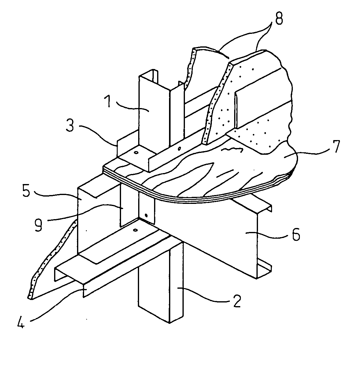
[0028] In FIG. 3, a joint structure according to the present invention, for fastening and joining the respective frame members with each other, is shown. In the drawing, a frame member 1 constitutes a pillar for an upper story and a frame member 2 constitutes a pillar for a lower story, and the ends of these frame members are orthogonally joined to tracks 3 and 4 to define a T-shape. Between the tracks 3 and 4, a sill 5 is disposed to be attached thereto, and another sill 6 is attached to the sill 5 and extends in the vertical direction. Directly above this sill 6, a floor 7 is placed. On the opposite sides of the sill 5, side wall members 8 are attached. Since the frame members 1 and 2 do not constitute an integral structure passing through the upper and lower stories but are assembled, a space exists between the both, in which the sills 5 and 6 are interposed. In this space, the s...


PUM


Abstract

The present invention provides a joint structure for a building using thin and lightweight shaped-steel, and, in particular, provides a joint structure for fastening and fixing frame members made of thin and lightweight shaped-steel to steel sills and a bolt joint truss structure for forming a main structure of a roof, sufficiently durable against a large earthquake or a strong wind such as a typhoon. A joint structure of a building using thin and lightweight shaped-steel is provided wherein, in a joint portion for fastening a steel frame member for forming a wall to a steel floor sill, a steel reinforcing member having a cross-sectional area in a range from 70 to 100% of a cross-sectional area of the steel frame member is inserted into the joint portion and fixed thereto. Also, a joint structure of a building using thin and lightweight shaped-steel is provided, wherein upper chord members, lower chord members and lattice members of light and lightweight shaped-steel are combined to form a truss structure, wherein a joint portion of the upper chord member, lower chord member and lattice member has at least one joint through-hole, and wherein the joint portions of the respective members are connected together to form a joint and a fastener is inserted into the joint through-hole to fasten and fix the respective members to each other.

Description

BACKGROUND OF THE INVENTION [0001] 1. Field of the Invention [0002] The present invention relates to a joint structure of a building using thin and lightweight shaped-steel, particularly a joint structure of an earthquake-resistant and wind-resistant building made of steel, for fastening a frame member made of thin and lightweight shaped-steel and a steel sill, and a bolt-joint truss structure constituting a main structure of a roof. [0003] 2. Description of the Related Art [0004] Recently, earthquake-resistant and wind-resistant steel building are in demand. These steel buildings are constructed by shaped-steel members obtained by roll-forming a thin steel sheet, of 2.3 mm thickness or less, which members are used as frame members, sills or roof members as they are roll-formed or after being bent, wherein the respective members are fastened together directly or via a reinforcement member by screws to form a building frame. In the prior art, there are a number of joints in steel bui...

Claims


Application Information

Patent Timeline
Patent Type & Authority Applications(United States)
IPC IPC(8): E04B1/24E04C3/04E04C3/07E04C3/11E04H9/14
CPCE04B1/2403E04B2001/2415E04B2001/2448E04B2001/2481E04B2001/2484E04C3/07E04H9/14E04C2003/0413E04C2003/0421E04C2003/0434E04C2003/0452E04C2003/0473E04C2003/0491E04C3/11
Inventor KAWAI, YOSHIMICHISHIMIZU, JUN
Owner NIPPON STEEL CORP
Why Eureka
Try Eureka