
Nasal ventilation interface

a ventilation interface and nasal tube technology, applied in the direction of breathing masks, inhalators, breathing protection, etc., can solve the problems of obstructive sleep apnea syndrome, affecting the sleep quality of patients, and affecting the quality of life of patients,

Inactive Publication Date: 2005-06-09
INNOMED TECH
View PDF13 Cites 97 Cited by
  • Summary
  • Abstract
  • Description
  • Claims
  • Application Information

AI Technical Summary

Problems solved by technology

However, in those individuals having a relatively smaller sized throat passage, the narrowed throat passage prohibits the adequate amount of oxygen from flowing into the lungs.
Additionally, a nasal obstruction, such as a relatively large tongue, and / or certain shapes of the palate and / or the jaw of the individual further prohibit the adequate amount of oxygen from flowing into the lungs.
As a result, the individual suffering from obstructive sleep apnea syndrome generally experiences fragmented sleep that is not restful.
The fragmented sleep results in one or more of excessive and / or inappropriate daytime drowsiness, headache, weight gain or loss, limited attention span, memory loss, poor judgment, personality changes, lethargy, inability to maintain concentration, and / or depression.
Further, prior to, during, and / or subsequent to certain medical procedures and / or medical treatments, an individual can be unable to receive the adequate amount of oxygen.
As a result, the harness is generally uncomfortable to wear, particularly when sleeping.
The applied pressure often results in undesirable irritation and sores caused by movement of the mask and harness during periods of both wakefulness and sleep.
Further, the required seal is generally difficult to maintain when the mask and harness is moved.
The mask also generally applies an undesirable pressure to the sinus area that is adjacent to the nose, causing the nasal sinus airways to narrow.
Additionally, the tubing may fold undesirably exacerbating the above problem.
The above-discussed combination of increased flow velocity and decreased pressure results in the removal of moisture from the mucosal walls during inspiration and may cause an undesirable drying and a burning sensation within the nares.
As a result, the individual may remove the mask to alleviate these discomforts, consequently discontinuing the beneficial application of the positive pressure.
Additionally the decreased pressure and increased air flow velocity deteriorate the laminar flow between the air input and output portions of the conventional mask.
This straight airflow may result in sub-optimal air flow towards the upper nasal passages and potential discomfort and poor ergonomics.

Method used


Image

  • Nasal ventilation interface
  • Nasal ventilation interface
  • Nasal ventilation interface

Examples


Embodiment Construction

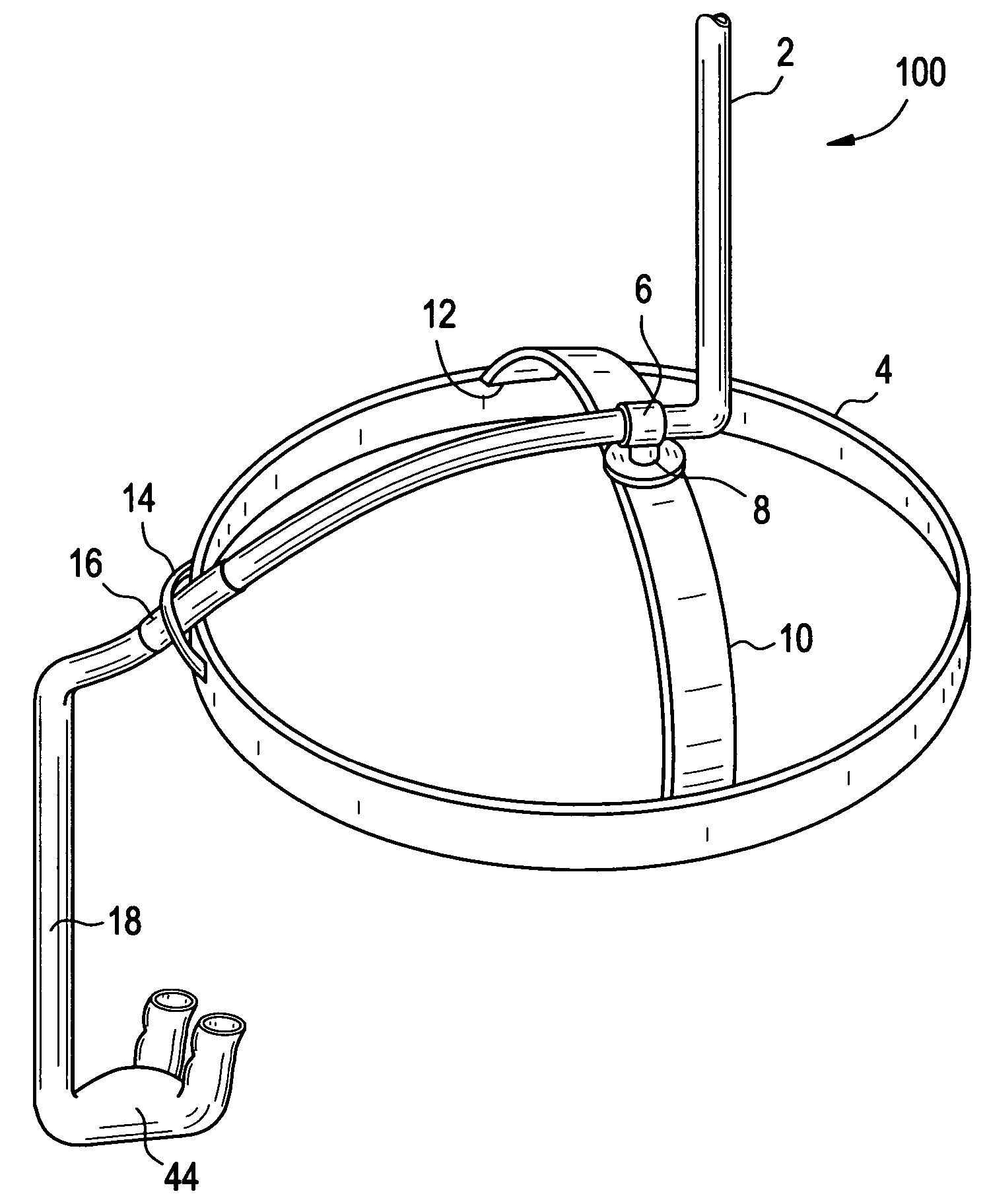
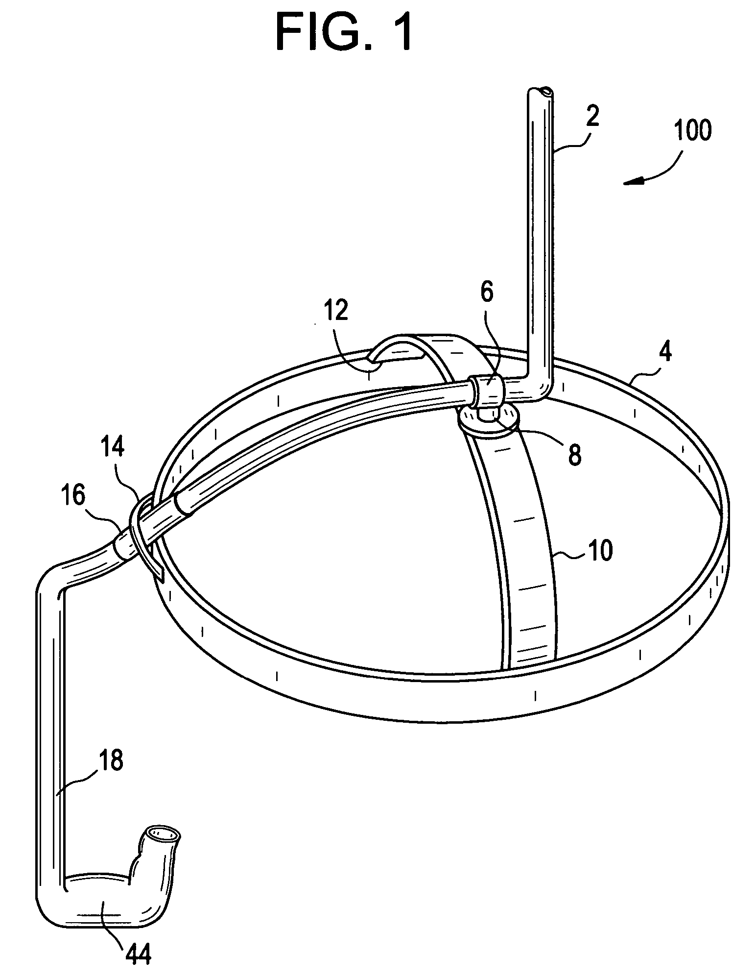
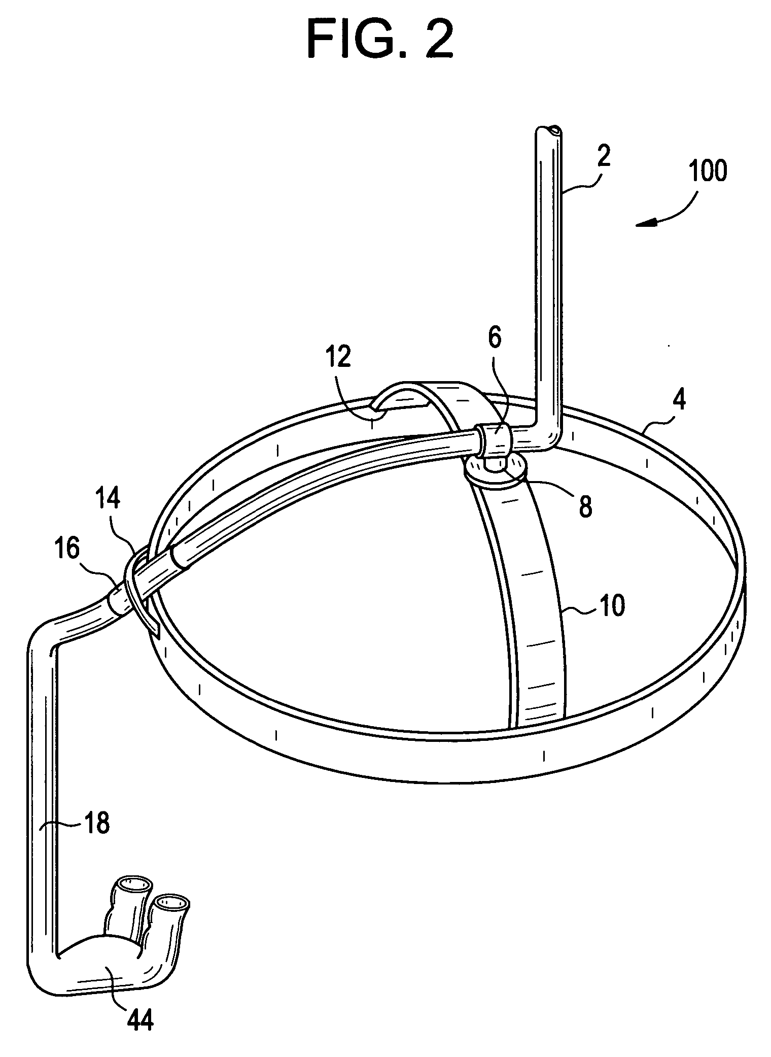
[0014] A first exemplary embodiment of the present invention provides a nasal ventilation interface including a cannula connectable to a source of ventilation. The nasal ventilation interface further includes at least one curved nasal insert and a central reservoir with at least one exhaust port.

[0015] In another exemplary embodiment the present invention provides a nasal ventilation interface including a headgear with a cross bar configured to receive tubing. The nasal ventilation interface further includes a cannula with at least one substantially curved nasal insert and at least one exhaust port. The tubing may be configured to pass through the headgear and is connected to a source of ventilation gas at a first end and connected with the cannula at a second end.

[0016] In yet another exemplary embodiment the present invention provides a method of wearing a nasal ventilation interface. The method includes connecting tubing to a source of ventilation at a first end. Connecting the...


PUM


Abstract

A ventilation interface and system is described which can be adapted to be connected to a source of ventilation. The ventilation interface and system may include improved headgear and nasal inserts with a curve.

Description

CROSS-REFERENCE TO RELATED APPLICATION [0001] This application claims the benefit of priority under 35 U.S.C. 119 to U.S. Provisional Patent Application No. 60 / 493,325 entitled “REM-PAP” filed Aug. 8, 2003, the disclosure of which is expressly incorporated by reference herein in its entirety.BACKGROUND OF THE INVENTION [0002] 1. Field of the Invention [0003] Exemplary embodiments of the invention are directed to a nasal ventilation interface adaptable to be connected to a source of ventilation. [0004] 2. Discussion of Related Art [0005] Obstructive sleep apnea syndrome (commonly referred to as obstructive sleep apnea, sleep apnea syndrome, and / or sleep apnea) is a medical condition which includes repeated, prolonged episodes of cessation of breathing during sleep. During a period of wakefulness, the muscles of the upper part of the throat passage of an individual keep the passage open, thereby permitting an adequate amount of oxygen to flow into the lungs. During sleep, the throat p...

Claims


Application Information

Patent Timeline
Patent Type & Authority Applications(United States)
IPC IPC(8): A61MA61M16/06A62B7/00A62B18/00
CPCA61M16/0683A61M16/0666
Inventor WOOD, THOMAS J.
Owner INNOMED TECH
Features
  • Generate Ideas
  • Intellectual Property
  • Life Sciences
  • Materials
  • Tech Scout
  • Unparalleled Data Quality
  • Higher Quality Content
  • 60% Fewer Hallucinations
Learn More