Composite heatsink for cooling of heat-generating element

a heat-generating element and heat-sink technology, applied in the field of heat-sinks, can solve the problems of premature device failure, reduced heat-removal cooling system effectiveness, and insufficient effectiveness of traditional heat-removal cooling system

Inactive Publication Date: 2005-06-09
ROTYS
View PDF6 Cites 19 Cited by
  • Summary
  • Abstract
  • Description
  • Claims
  • Application Information

AI Technical Summary

Benefits of technology

[0010] According to the present invention the general idea is to increase the heat-exchanging surface at the same volume of the heatsink due to the smaller spacing between heat-exchanging means without arising additional thermal resistance.

Problems solved by technology

But, according to these technologies there are some limitations in respect to the distance between fins.
Cooling is important because if left unchecked, heat can cause electronic devices to malfunction during use or lead to premature device failure.
The trend toward smaller electronic devices demanding smaller coolers and having larger, faster processors renders the traditional heat removal cooling systems less effective or inadequate.
But, such junction of the fins with the base leads to arising additional thermal resistance between the base and the fins and, therefore, to some decreasing of heat exchange efficiency of the heatsink.
And more, such known heatsink design requires more expensive technologies.

Method used


Image

  • Composite heatsink for cooling of heat-generating element
  • Composite heatsink for cooling of heat-generating element
  • Composite heatsink for cooling of heat-generating element

Examples


Embodiment Construction

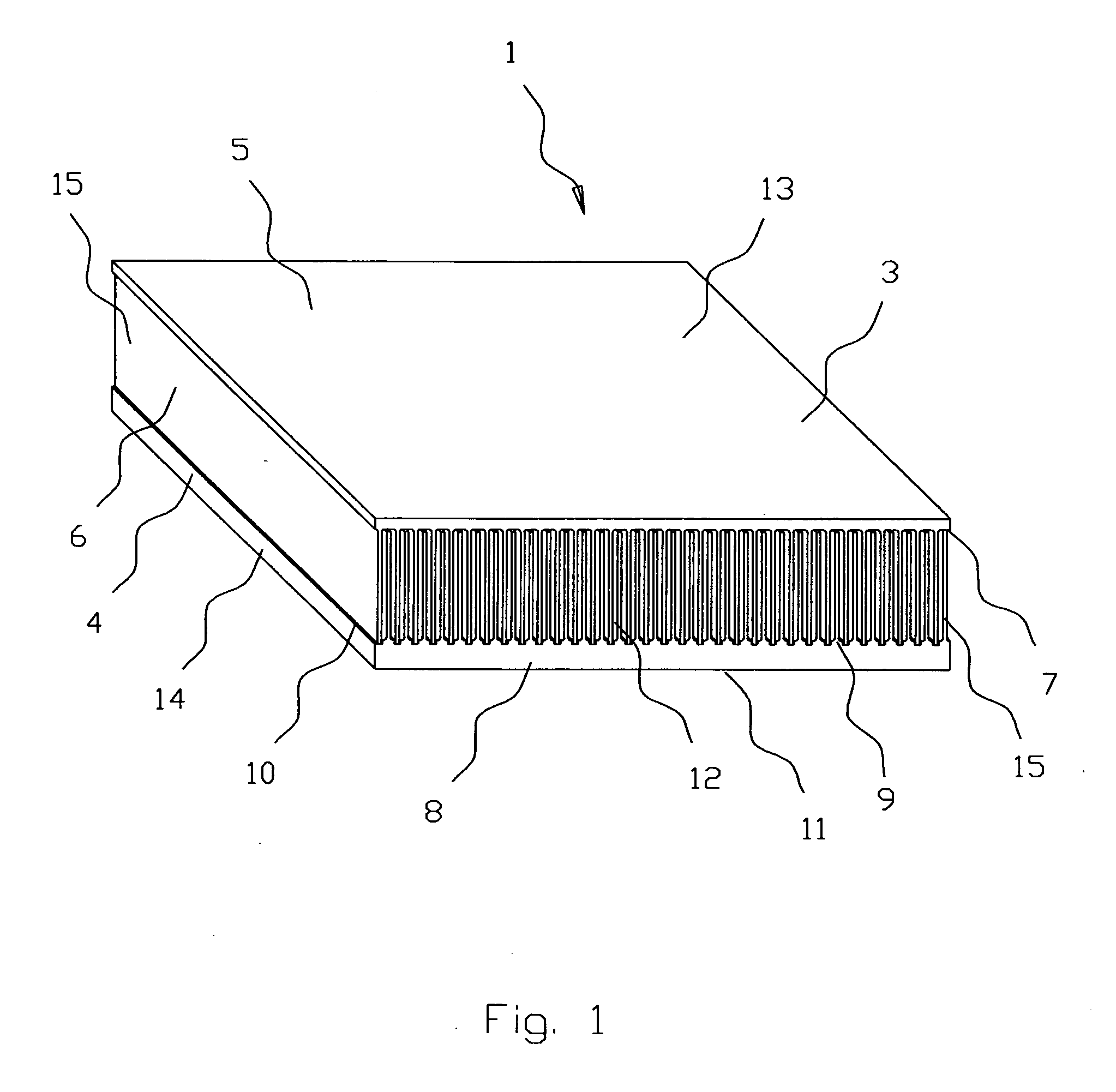
[0021] Preferred embodiment of the present invention will be described in detail below with reference to the accompanying drawings. FIGS. 1-4 show embodiment of the present invention.

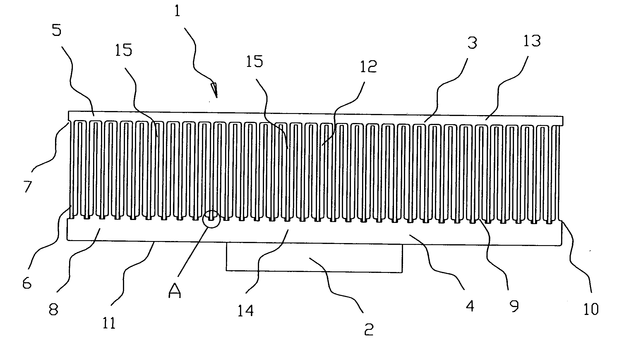
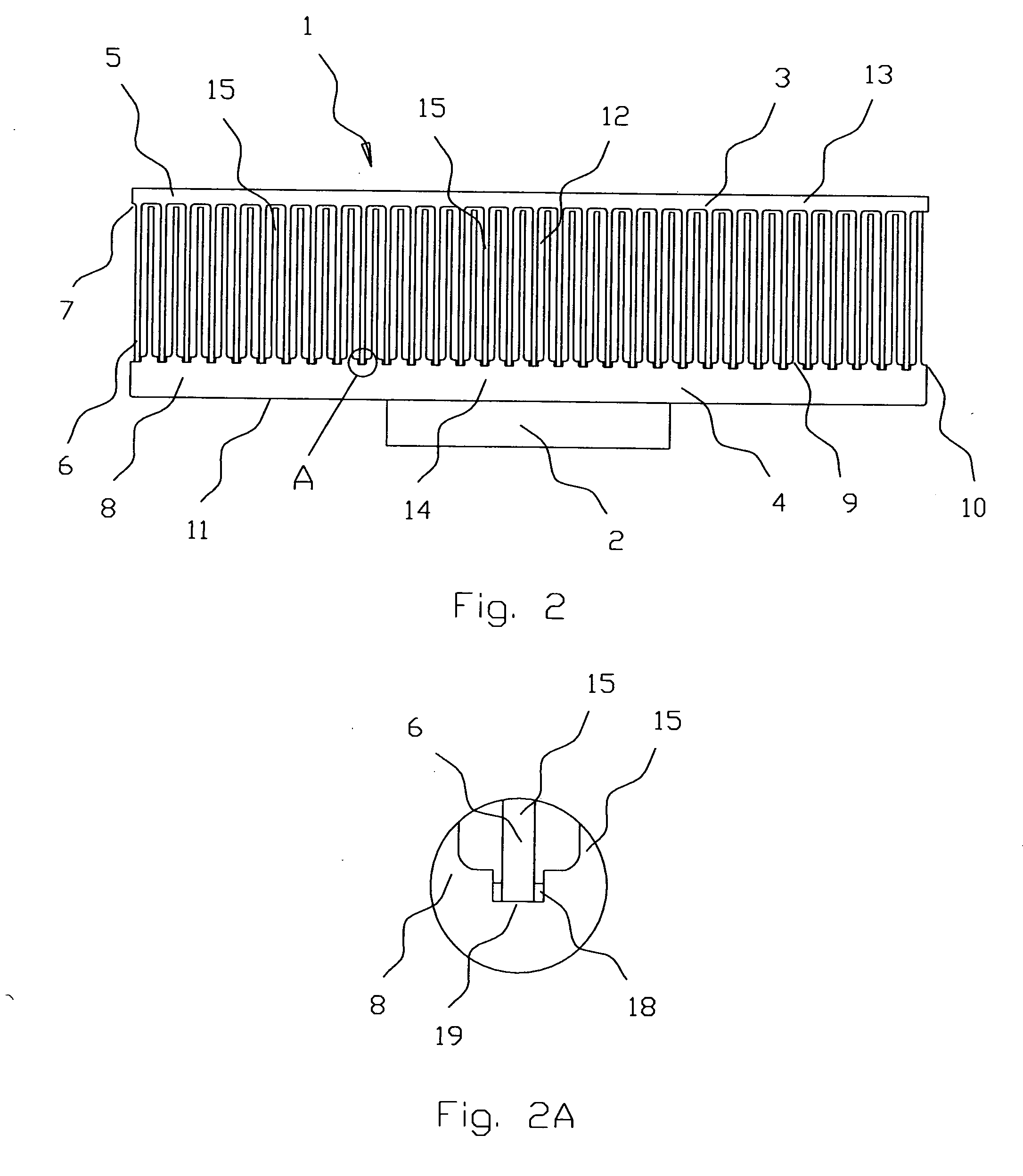
[0022] A composite heatsink 1 (FIG. 1-2) for cooling of heat-generating element 2 comprises upper 3 and lower 4 components. The upper component 3 (FIG. 3) comprises a cover plate 5 and a first set 6 of heat-exchanging means thermally connected with one side 7 of the cover plate 5.

[0023] The lower component 4 (FIG. 4) comprises a base 8 and a second set 9 of heat-exchanging means thermally connected with one side 10 of the base 8 while the other side 11 of the base 8 thermally connected with the heat-generating element 2. The first set 6 of heat-exchanging means located in alternate order in respect to the second set 9 of heat-exchanging means and thermally connected with the base 8 from a side 10 opposite to the heat-generating element 2, thus forming a plurality of heat exchange channels 12.

[0024] A...


PUM


Abstract

A composite heatsink for cooling of heat-generating element comprises upper and lower components. The upper component comprises a cover plate and a first set of heat-exchanging means thermally connected with one side of the cover plate. The lower component comprises a base and a second set of heat-exchanging means thermally connected with one side of the base while the other side of the base thermally connected with the heat-generating element. The first set of heat-exchanging means located in alternate order in respect to the second set of heat-exchanging means and thermally connected with the base from a side opposite to the heat-generating element, thus forming a plurality of heat exchange channels. The upper and lower components could be made using the extrusion, forging or die casting technologies. The first and second sets of heat-exchanging means could be made like parallel fins with the same equal spacing located perpendicularly to the cover plate and the base, correspondingly.

Description

CROSS REFERENCE TO RELATED APPLICATIONS [0001] The present application claims the benefit of priority of U.S. Provisional Patent Application No. 60 / 526,917, filed Dec. 3, 2003 for Edward Lopatinsky the entire content of which is incorporated herein by reference.FIELD OF THE INVENTION [0002] The present invention relates generally to heat-exchanging equipments, and more particularly, to the heatsinks with heat-exchanging means made as fins and / or pins. The present invention is particularly, but not exclusively, useful for cooling systems for regulating the temperature of electronic components. BACKGROUND OF THE INVENTION [0003] There are known many types of heatsinks have been known in prior arts. One type of them is the heatsinks comprising a base and heat-exchanging means made as fins and / or pins-fins structures. The most of such heatsinks made as a whole. For example, U.S. Pat. No. 6,667,884 “Heat Dissipating Assembly” comprises the heatsink made as a whole of fins and a base. The...

Claims


Application Information

Patent Timeline
Patent Type & Authority Applications(United States)
IPC IPC(8): H01L23/367H05K7/20
CPCH01L23/3672H01L2924/0002H01L2924/00
Inventor LOPATINSKY, EDWARD
Owner ROTYS
Why Eureka
Try Eureka