
Heat exchanger for washing machine

A technology for heat exchangers and washing machines, applied in other washing machines, applications, washing devices, etc., can solve the problems of low utilization rate of heat energy and high power consumption, so as to improve the utilization rate of heat energy, high heat exchange efficiency, and increase flow through effect of time

Inactive Publication Date: 2015-12-09
蒋凤英
View PDF9 Cites 0 Cited by
  • Summary
  • Abstract
  • Description
  • Claims
  • Application Information

AI Technical Summary

Problems solved by technology

The pulsator washing machine has the advantages of easy cleaning of the filter and small space occupied by the horizontal fan, but it also has no heat exchanger, so it also has the disadvantages of low heat energy utilization rate and high power consumption in the drying process.

Method used


Image

  • Heat exchanger for washing machine
  • Heat exchanger for washing machine
  • Heat exchanger for washing machine

Examples


Embodiment 1

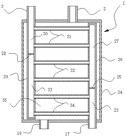
[0016] Such as figure 1 As shown, the heat exchanger 1 of the present embodiment includes a shell 24 and a heat exchange tube, and the heat exchange tube is arranged in the shell 24; the heat exchange tube includes a left vertical pipe 29 and a right vertical pipe 26 and 6 horizontal tubes; the left vertical tube 29 and the right vertical tube 26 are provided with 1 (n=1) partition layers (28, 25), and the left vertical tube 29 and the right vertical tube 26 are from top to bottom The bottom is divided into the first tube space (30, 27) and the second (n+1=2) tube space (33, 23) which are not connected to each other by the one partition layer (28, 25); the horizontal tube The left ends of each are connected with the left vertical pipe 29, and the right ends are connected with the right vertical pipe 26.

[0017] The horizontal tubes are divided into 3 (2*n+1=3) groups; each horizontal tube of the i (i=1, 2, 3 (2*n+1=3)) group of horizontal tubes is connected with all the hori...

Embodiment 2

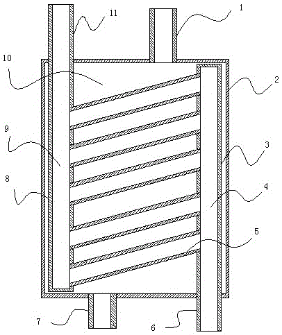
[0025] Such as image 3As shown, this embodiment includes a shell 2 and a heat exchange tube, and the heat exchange tube is arranged in the shell 2 . The heat exchange tubes include a left vertical tube 8 , a right vertical tube 3 and five horizontal tubes 5 . The left vertical pipe 8 and the right vertical pipe 3 are provided with 0 (n=0) partition layers, and the tubes of the left vertical pipe 8 and the right vertical pipe 3 are separated from top to bottom by the 0 partition layers. The first (n+1=1) tube space (9, 4) that is not connected; the left end of the horizontal tube 5 is connected to the left vertical tube 8, and the right end is connected to the right vertical tube 3 .

[0026] The horizontal tubes 5 are divided into 1 (2*n+1=1) groups; each horizontal tube of the i (i=1(2*n+1=1)) group of horizontal tubes is connected to the left vertical tube The xth pipe space of the pipe 8 and the yth pipe space of the right vertical pipe 3 are connected, wherein x is a m...


PUM


Abstract

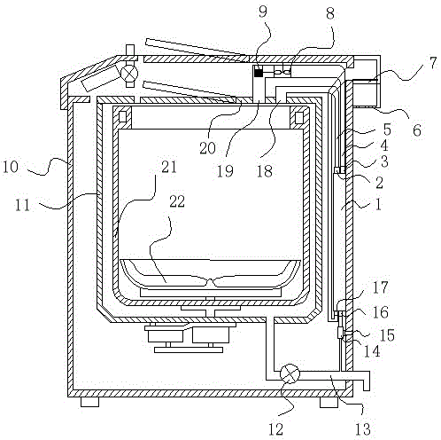
The invention discloses a heat exchanger for a washing machine. The heat exchanger comprises a shell and one or more heat exchange tubes, wherein the heat exchange tubes are arranged in the shell, a damp and hot air inlet and a cold air outlet are formed in the upper side of the shell, and a damp and hot air outlet and a cold air inlet are formed in the lower side of the shell. According to the washing machine additionally provided with the heat exchanger, damp and hot air can be led into the heat exchanger after being used for drying clothes, an inner cylinder and an outer cylinder, then the damp and hot air preheats cold air to be heated by an electric heater in the heat exchanger, and in this way, the heat energy utilization rate of the washing machine can be increased; meanwhile, electricity consumption is reduced in the drying process of the washing machine.

Description

technical field [0001] The invention relates to the field of household appliance components, in particular to a heat exchanger for a washing machine. Background technique [0002] At present, people's functional requirements for washing machines are not limited to washing, rinsing, disinfection, dehydration, etc., and washing machines with drying function are more and more popular. Existing washing machine with drying function, such as a kind of washing machine that can send warm air into the inner barrel for laundry to be put into as the Chinese invention patent of application number 03138545.1, comprises casing, outer barrel, inner barrel and The warm air supply device, the inner barrel is rotatably arranged in the outer barrel, the outer barrel cover is provided above the outer barrel, and the casing cover is provided above the casing; the warm air supply device is arranged above the inside of the casing, And send warm air into the inner barrel from the warm air supply p...

Claims


Application Information

Patent Timeline
IPC IPC(8): D06F39/04D06F39/00
CPCD06F39/00D06F39/04
Inventor 蒋凤英熊飞彪
Owner 蒋凤英
Learn More