Millimeter-wave active imaging system

Active Publication Date: 2005-06-09
L3 COMMUNICATIONS SECURITY & DETECTION SYSTEMS CORPORATION
View PDF22 Cites 28 Cited by
  • Summary
  • Abstract
  • Description
  • Claims
  • Application Information

AI Technical Summary

Benefits of technology

[0004] Various configurations of an antenna apparatus are possible. A particular configuration can be selected as appropriate for a particular application. For example, the antenna apparatus may include one or a plurality of antenna units, such as a linear or two-dimensional array of antenna units. The antenna unit or units may move along a curved path or be in an array that is curved or straight, and may be fixed or move in a curved or straight path. Antenna units or one or more arrays of antenna units may be fixed in position and pivot to scan a subject from

Problems solved by technology

This is particularly true in situations where the surveillance delays the intended progress of the person being surve

Method used


Image

  • Millimeter-wave active imaging system
  • Millimeter-wave active imaging system
  • Millimeter-wave active imaging system

Examples


Embodiment Construction

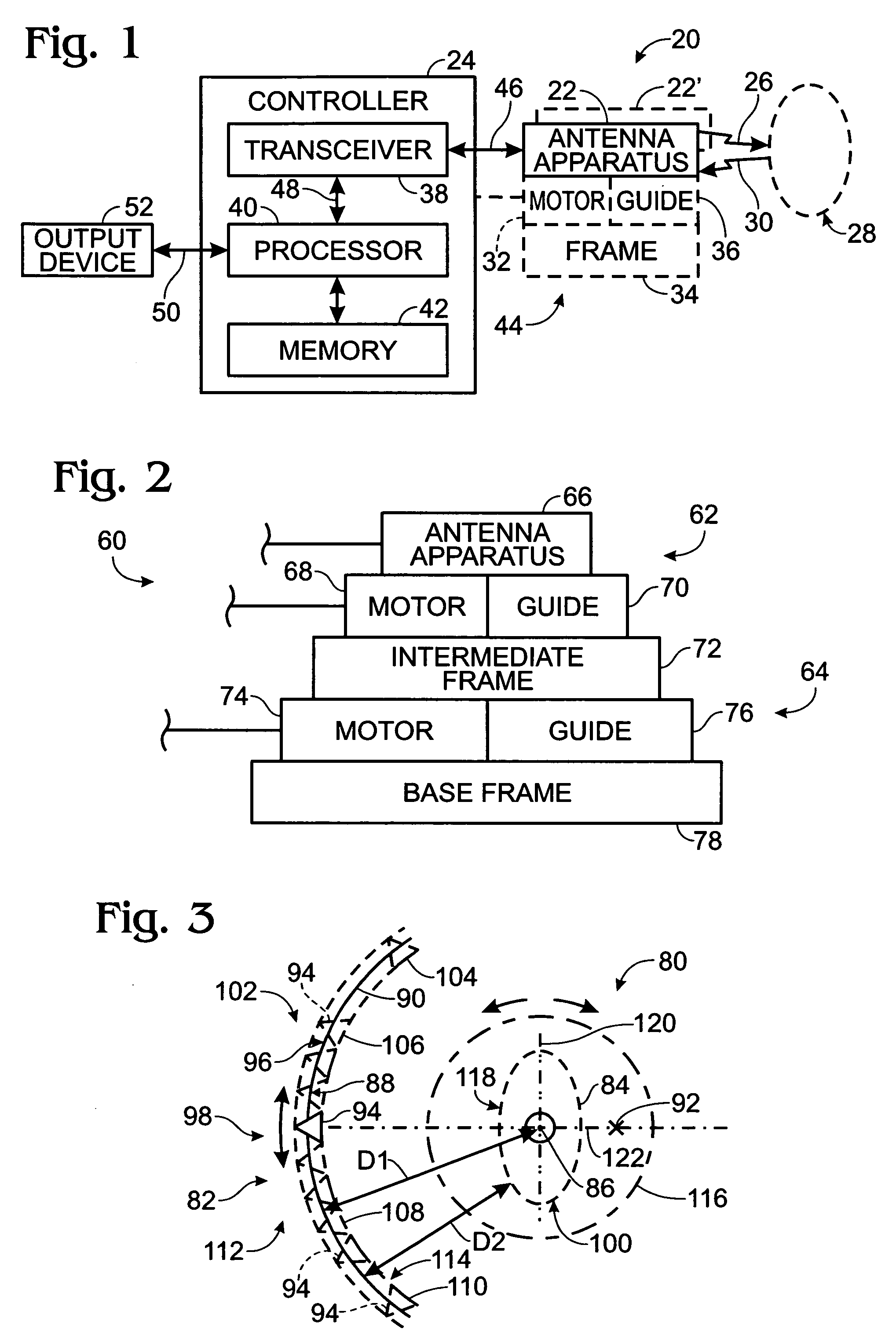
[0019] Shown generally at 20 in FIG. 1 is an active imaging system. System 20 includes an antenna apparatus 22 and a controller 24. The system is active in the sense that the antenna apparatus transmits electromagnetic radiation 26 toward a subject 28, and in response, the subject emits or reflects electromagnetic radiation 30 that is detected by the antenna apparatus. A subject includes all that is presented in an interrogation station of an imaging system for imaging, whether human, animal, or inanimate object. For example, if a person is in an interrogation station for imaging, the subject includes the person as well as any objects supported on the person, such as watches, keys, jewelry, pocket or other knives, coins, clothing accessories, guns, or any other objects that can be imaged. A subject may include one or more persons, animals, objects, or combination of these.

[0020] Electromagnetic radiation may be selected from an appropriate frequency range, such as in the range of a...


PUM


Abstract

Active millimeter-wave imaging systems can include an antenna apparatus configured to transmit toward and receive from a subject in a subject position, electromagnetic radiation. A controller can include a transceiver configured to operate the antenna apparatus and produce an output representative of the received radiation, and a processor adapted to convert the transceiver output into image data representative of an image of the subject. The antenna apparatus may move in a partial or continuous loop around the subject, toward or away from the subject, or in an opposite direction to an associated antenna apparatus. Antenna units in the antenna apparatus may be oriented at different angular positions along an array. Antenna arrays may also be formed of a plurality of array segments, and a group of arrays may be combined to form an antenna apparatus.

Description

BACKGROUND [0001] Millimeter Wave signals are used for radar and telecommunications. They are also capable of being used for producing an image of a subject by directing millimeter-wave signals at the subject and detecting the reflected signal. Examples of such imaging systems have been described in U.S. Pat. Nos. 5,455,590; 5,557,283; 5,859,609; and 6,507,309; and U.S. patent application Ser. No. 10 / 607,552 filed Jun. 26, 2003 and a continuation-in-part of that application filed Oct. 30, 2003 entitled “Detecting Concealed Objects at a Checkpoint”; and U.S. patent application Ser. No. 10 / 301,522 filed Nov. 21, 2002 and a continuation-in-part of that application filed Oct. 30, 2003 entitled “Detection of a Concealed Object”, which patent references are incorporated herein by reference. [0002] When imaging systems are used for surveillance of persons, it may be desirable for the system to quickly, conveniently and safely perform the surveillance. This is particularly true in situation...

Claims


Application Information

Patent Timeline
IPC IPC(8): G01S13/89G01V8/00H01Q3/04
CPCG01S13/887H01Q3/04G01V8/005G01S13/89
Inventor GRUDKOWSKI, THOMAS W.ROWE, RICHARD L.BLASING, RAYMOND R.TROSPER, SCOTT T.TRAWICK, THOMAS W.MEYER, KAREN A.GENSKE, DAVID J.VAN EYCK, GERALD J.DRINKERHOFF, MARK D.
Owner L3 COMMUNICATIONS SECURITY & DETECTION SYSTEMS CORPORATION
Why Eureka
Try Eureka