Liquid crystal display device and driving device thereof, and method for driving liquid crystal display device

a liquid crystal display and driving device technology, applied in static indicating devices, non-linear optics, instruments, etc., can solve the problems of deteriorating displaying quality, slow response speed becomes a big problem, ghosting of moving pictures, etc., to improve displaying quality and improve response speed

Active Publication Date: 2005-06-09
UNIFIED INNOVATIVE TECH
View PDF9 Cites 54 Cited by
  • Summary
  • Abstract
  • Description
  • Claims
  • Application Information

AI Technical Summary

Benefits of technology

[0020] In view of the foregoing problems, an object of the present invention is to provide a liquid crystal display device which can improve a displaying quality by grasping an actual temperature of displaying element in pixels, and improving a response speed based on the actual temperature measured. It is also the object of the present invention to provide the liquid crystal display device and a driving device thereof as well as a method of driving the liquid crystal display device, in which it is possible to drive each of scan signal lines on a line-by-line basis, and to more appropriately carry out overshooting, regardless of unevenness in temperatures within the displaying area of the liquid crystal display device.
[0025] Thus, it is possible to provide the liquid crystal display device which can improve the displaying quality by measuring the actual temperature of the liquid crystal element in the pixels, and improving the response speed based on the actual temperature measured.
[0034] As a result, it is possible to provide the liquid crystal display device and the method therefor, in which the overshooting is optimized even if the temperatures get uneven within the displaying area.

Problems solved by technology

In the liquid crystal display device, a slow response speed becomes a big problem in displaying the moving picture on a liquid crystal module.
More specifically, when the moving picture is displayed on the liquid crystal display device whose response speed is slow, after-image appear on the screen, thus causing ghosting of the moving picture.
This causes deterioration in displaying quality.
Therefore the liquid crystal display device cannot display natural-color moving pictures without significant deterioration in display quality in some frames.
This method, however, does no more than rough correction in response to the changes in the temperature by referring to the estimated temperature of the liquid crystal panel based on the temperatures at the edges of the liquid crystal panel.
Therefore, even by the arrangement in which the liquid crystal panel is divided into the four regions, there still remains a problem that it is impossible to accurately compensate a driving voltage for the actual temperature changes in the four regions.
Therefore, the aforementioned drawback is an important problem in the overshoot method.
However, the response speed of the liquid crystal largely depends on temperature of the liquid crystal itself, and the response speed becomes dramatically slow at a low temperature of the liquid crystal.
Further, more-than-necessary overshooting causes the liquid crystal to respond more than necessary.
Such more-than-necessary response causes a displayed image to look unnatural.
Further, alongside the development of larger liquid crystal display devices in recent years, the problem of the liquid crystal temperature unevenness (unevenness in the temperature of the liquid crystal) in the displaying section is becoming increasingly important.
Especially, there is no attempt to perform correction to compensate for the temperature unevenness in the display region.

Method used


Image

  • Liquid crystal display device and driving device thereof, and method for driving liquid crystal display device
  • Liquid crystal display device and driving device thereof, and method for driving liquid crystal display device
  • Liquid crystal display device and driving device thereof, and method for driving liquid crystal display device

Examples


embodiment 1

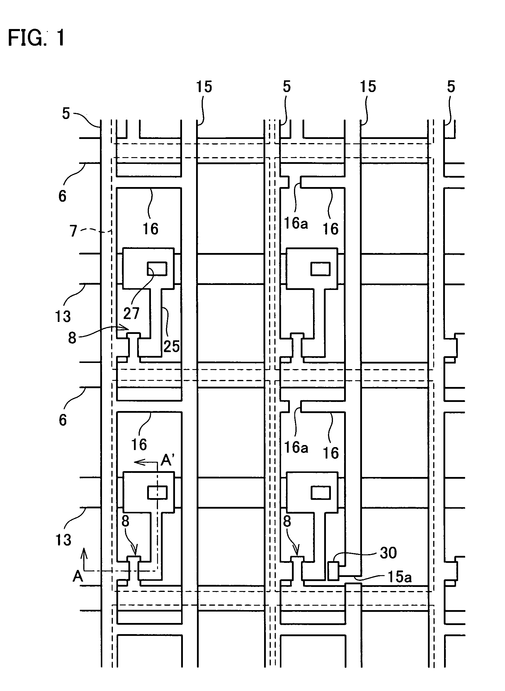
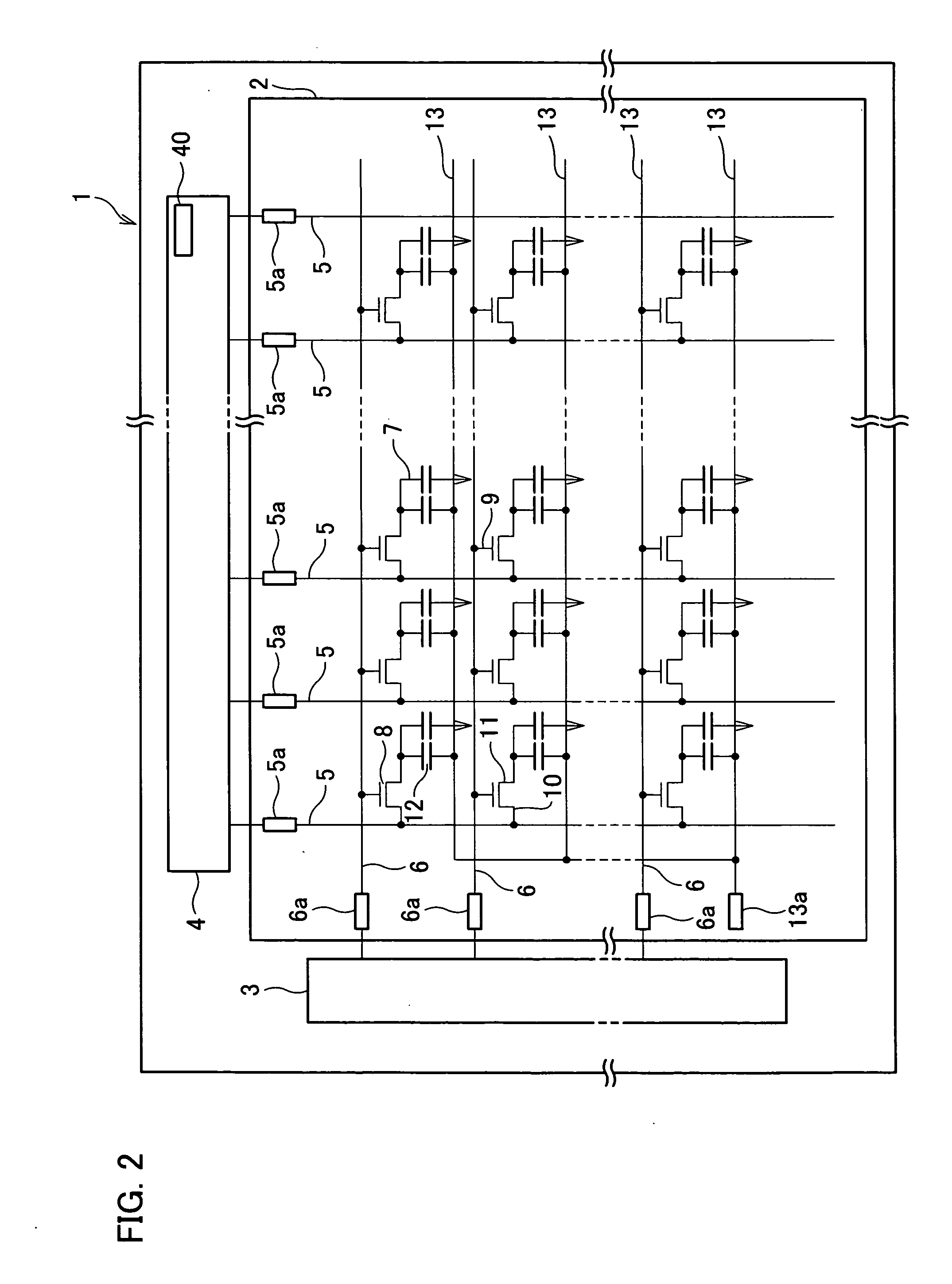
[0059] An embodiment of the present invention is described as follows with reference to FIGS. 1 through 9.

[0060] As shown in FIG. 2, in the present embodiment, a liquid crystal display device 1 which is an active matrix type display device, includes a display panel 2 serving as a displaying section, a scan-signal-line driving section 3 for outputting a scan signal, and a data-signal-line driving section 4 serving as data-signal-line driving means for applying a data signal (i.e. video signal). For example, the display panel 2 is provided with (i) a pair of glass substrates (a first glass substrate and a second glass substrate) arranged in parallel to each other, (ii) polarizers respectively formed on outer surfaces of the first and second glass substrates, (iii) transparent electrodes respectively formed on inner surfaces of the first and second glass substrates, (iv) alignment films formed on the transparent electrodes, (v) liquid crystal between the first and second glass substra...

embodiment 2

[0123] Another embodiment of the present invention is described below with reference to FIGS. 3, 10(a) to 10(c) and 11. The same symbols are given to the members that have the same functions as those shown in figures of the foregoing embodiment 1, and the descriptions of those members are omitted here as a matter of convenience. It should be noted that the liquid crystal display device described in the foregoing embodiment 1 with reference to FIG. 2 is referred to as a liquid crystal display unit in the present embodiment as well as in later described embodiments 3 and 4.

[0124] As shown in FIG. 11, in the present embodiment, a liquid crystal display device 100 which is an active matrix type display device, includes a liquid crystal display unit 105. This liquid crystal display unit 105 includes a display panel 2 serving as a displaying section, a scan-signal-line driving section 3 for outputting a scan signal, and a data-signal-line driving section 4 serving as data-signal-line dri...

embodiment 3

[0160] The following describes another embodiment of the present invention with reference to FIG. 12(a) and FIG. 12(b). It should be noted that features of the present embodiment are the same as those described in the foregoing embodiment 2 unless otherwise described hereinbelow. Further, the same symbols are given to the members that have the same functions as those shown in figures of the foregoing embodiments 1 and 2, and the descriptions of those members are omitted here as a matter of convenience.

[0161] In addition to the configuration as described in the foregoing embodiment 1, a liquid crystal display device 110 of the present embodiment is provided with a driving device 60 having a temperature sensor 61 in a displaying area of a display panel 2 (See FIG. 12(a)). The temperature sensor 61 is used for obtaining temperature transition information. The temperature transition information is recorded in a memory 63 (data generating section selecting means) for use in switching da...


PUM


Abstract

A liquid crystal display device of the present invention includes (i) a temperature sensor provided in at least one of pixels in a displaying area of a display panel, (ii) a lead line buried in the display panel, for transmitting a detection signal from the temperature sensor to a vicinity of the display panel, (iii) a temperature measurement control section for measuring a pixel temperature based on the detection signal transmitted from the temperature sensor, (iv) a data signal line driving section for outputting the data signal to the data signal lines in accordance with the pixel temperature measured in the temperature measurement control section. Further, the liquid crystal display device of the present invention includes (i) a plurality of data generating sections for generating data signals of the different output levels based on an inputted video signal and a video signal that is at least one frame earlier than the inputted video signal, (ii) a data generating section containing section for containing therein the plurality of the data generating sections, and (iii) a memory for use in selecting one of the data generating sections on a line-by-line basis for the respective scan signal lines.

Description

[0001] This Nonprovisional application claims priority under 35 U.S.C. § 119(a) on Patent Applications No. 2003 / 404912 filed in Japan on Dec. 3, 2003, and No. 18612 / 2004 filed in Japan on Jan. 27, 2004, the entire contents of which are hereby incorporated by reference. FIELD OF THE INVENTION [0002] The present invention relates to a liquid crystal display device adopting a matrix type display section having a displaying element whose temperature dependency is large. The present invention also relates to a driving device for the liquid crystal display device, and a method for driving the liquid crystal display device. BACKGROUND OF THE INVENTION [0003] A liquid crystal display device has been used as a display device for a computer. In recent years, such liquid crystal display device comes into increasing use for displaying a moving picture. This is because (i) use of the liquid crystal display device as a television has been developed as a result of development of a larger liquid cr...

Claims


Application Information

Patent Timeline
Patent Type & Authority Applications(United States)
IPC IPC(8): G09G3/36
CPCG02F1/133382G09G3/3648G09G2320/0233G09G2340/16G09G2320/0261G09G2320/041G09G2320/0252
Inventor MURAO, MASAYUKIMIZUMAKI, HIDETAKA
Owner UNIFIED INNOVATIVE TECH
Why Eureka
Try Eureka