Communication terminal device

a terminal device and communication terminal technology, applied in the field of communication terminal devices, can solve the problems of affecting tv watching, unable to set an appropriate tv broadcasting frequency, and difficulty in reducing the size and cost of the communication terminal, and achieve the effect of improving usability

Inactive Publication Date: 2005-06-09
HITACHI LTD
View PDF6 Cites 41 Cited by
  • Summary
  • Abstract
  • Description
  • Claims
  • Application Information

AI Technical Summary

Benefits of technology

[0008] Accordingly, the present invention makes possible to provide a communication terminal devices which offer improved usability.

Problems solved by technology

However, the control method and apparatus described in JP-A-8-162909 must previously register a large number of base stations installed all over the country, positional information thereon, TV broadcast-ing frequencies, TV broadcasting receivable areas, and the like in correspondence to one another, and therefore fail to set an appropriate TV broadcasting frequency when a new base station is additionally installed or when an existing base station is removed from service.
In addition, the control method and apparatus described in JP-A-8-162909 not only entail complicated operations for the registration but also require a large capacity of memories for storing such a huge amount of information, leading to difficulties in reducing the size and cost of the communication terminal.
Further, since the huge amount of registered information must be searched for required information on an appropriate base station, positional information, TV broadcasting frequency, a TV broadcasting receivable area, and the like, TV broadcasting radiowaves cannot be normally received during the search, possibly causing fluctuations in a received video image which would interfere with TV watching.
The receiver described in JP-A-7-111439 in turn must continuously receive radiowaves from GPS satellites to monitor a current position at all times, and can therefore suffer from large power consumption and a reduced standby time.
In addition, when the receiver is situated in an underground town or street or the like where radiowaves from the GPS satellites do not reach, the receiver cannot set a TV broadcasting frequency because of the inability to acquire positional information.
Also, as is the case with JP-A-8-162909, the receiver is incapable of more promptly switching TV broadcasting frequency settings, it cannot normally receive TV broadcasting radiowaves during the switching, possibly causing fluctuations in a received video image which would interfere with TV watching.

Method used


Image

  • Communication terminal device
  • Communication terminal device
  • Communication terminal device

Examples


first embodiment

[0034] A first embodiment of the present invention will be described with reference to the accompanying drawings.

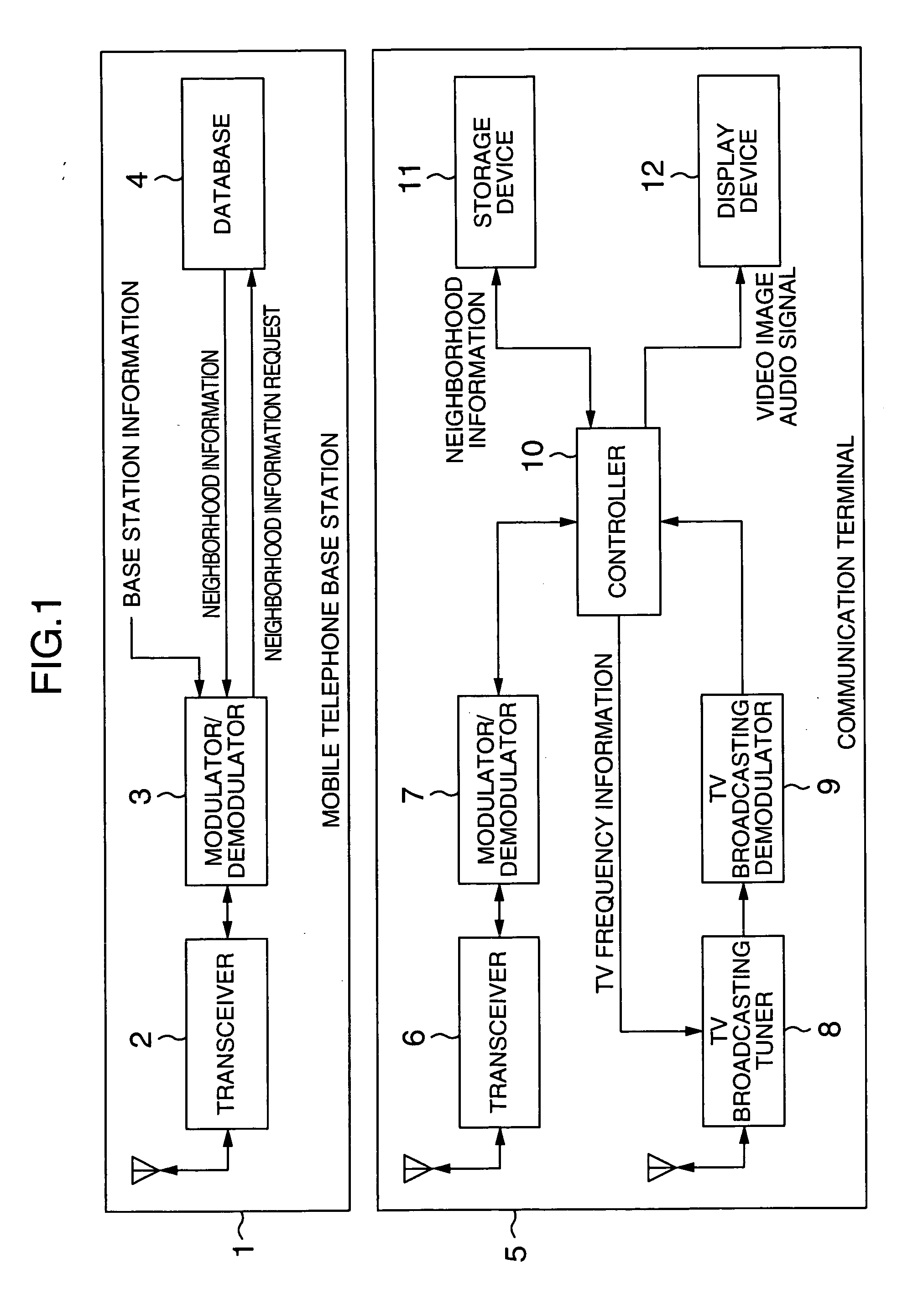
[0035] Referring first to FIG. 1, description will be made on the configuration of a communication terminal and a base station.

[0036] The base station 1 comprises a base station transceiver 2, and a bases station modulator / demodulator 3. The base station transceiver 2 communicates with the communication terminal 5 through a network. The bases station modulator / demodulator 3 modulates / demodulates information transmitted from or received by the base station transceiver 2.

[0037] A database 4 is a server for storing information such as a TV broadcasting receivable area in which the base station 1 is installed, a TV broadcasting frequency to which the communication terminal 5 should be set in this area, an adjacent TV broadcasting receivable area, a TV broadcasting frequency to which the communication terminal 5 should be set in this adjacent area, and the like, in correspo...

second embodiment

[0101] A second embodiment of the present invention will be described with reference to the accompanying drawings.

[0102] Referring first to FIG. 9, description will be made on the configuration of a communication terminal and a base station in the second embodiment.

[0103] A base station 1 is similar to that in the first embodiment (FIG. 1), so that description thereon is omitted.

[0104] While a communication terminal 5 is also substantially similar to that in the first embodiment (FIG. 1), the communication terminal 5 of the second embodiment differs in that an RFID signal transceiver 13 is added. RFID may be installed, for example, on a wall, a ceiling, a device, and the like, so that the RFID signal transceiver 13 receives positional information transmitted from the RFID. RFIDs are classified into one which transmits information on the position at which it is installed in response to a radio signal indicative of a request for positional information, and one which continues to tr...


PUM


Abstract

A communication terminal device comprising a TV broadcasting tuner for receiving a TV broadcasting, a display device for displaying a video image of the received TV broadcasting, and a transceiver for communicating with a base station. The transceiver acquires base station information for an optional one of base station areas, and acquires a TV broadcasting frequency corresponding to the optional base station area. The TV broadcasting tuner receives the TV broadcasting at the acquired TV broadcasting frequency.

Description

BACKGROUND OF THE INVENTION [0001] The present invention relates to a communication terminal device, for example, a communication terminal device which is capable of receiving television (TV) broadcasting. [0002] Conventionally, a method of setting a TV broadcasting frequency in a communication terminal capable of receiving TV broadcasting is proposed, for example, in JP-A-8-162909 which describes a control method and apparatus that involves acquiring positional information from information on a base station associated with a mobile telephone, and searching TV broadcasting frequencies previously registered in a communication terminal based on the positional information to set an appropriate TV broadcasting frequency to the communication terminal. [0003] Another similar technique proposed, for example, in JP-A-7-111439, which discloses a receiver that can automatically select a broadcasting station, involves comparing information on a current geographical position acquired through th...

Claims


Application Information

Patent Timeline
Patent Type & Authority Applications(United States)
IPC IPC(8): H03J5/02H04B1/16H04H20/00H04H20/57H04H60/42H04H60/51H04H60/85H04N5/44
CPCH04H20/26H04N21/4755H04H20/61H04H60/11H04H60/25H04H60/42H04H60/43H04H60/51H04H60/65H04H60/85H04H60/91H04H60/92H04N21/2265H04N21/41407H04N21/42202H04N21/438H04N21/4383H04N21/44209H04H20/57
Inventor KATSUBE, YUSAKUTERUI, KOICHI
Owner HITACHI LTD
Why Eureka
Try Eureka