Support arm for vehicle mirror

a technology for supporting arms and mirrors, which is applied in the direction of machine supports, instruments, other domestic objects, etc., can solve the problems of increasing the unfavorable effect of drive resistance and strain, aerodynamic disadvantage, and installation of mirrors, and achieves better attachment, reduced stability of mirror head-support arm connections, and high stability.

Active Publication Date: 2005-06-09
LANG MEKRA NORTH AMERICA LLC
View PDF3 Cites 8 Cited by
  • Summary
  • Abstract
  • Description
  • Claims
  • Application Information

AI Technical Summary

Benefits of technology

[0006] The metal tube is made integral with the holding arms providing a support arm having a high stability, especially when considering the wind load and the vibrations coming from the vehicle. Furthermore, it makes it possible to utilize mirror heads that were designed for traditional bracket tubes. Therefore, the same mirror heads can advantageously be utilized for both traditional tube brackets, as well as supporting arms.
[0007] As opposed to the above described one-piece plastic support arm, the metal tube especially offers the possibility for better attachment because corresponding attachment elements are attached directly to the metal tube and not to softer plastic. Up until now, with all known attachment types (positive fit, plug connections, screwing, clamping), the stability of the mirror head-support arm connection decreases as a result of aging and deterioration of the plastic.
[0008] As opposed to the familiar U-shaped tubing that is completely made of metal, the support arm has the advantage of reduced weight and greater design freedom with respect to aerodynamics. However, because the metal tube can be advantageously shaped to be identical to the cross web, the same mirror heads can be utilized.
[0009] To further strengthen the plastic holding arms, at least one of these arms can encompass one or several embedded parts, preferably of metal. In this way, it is advantageously possible to keep the wall thickness in especially stressed areas thin. This saves not only material costs, but also helps avoid an undesirable material depression in manufacturing.

Problems solved by technology

First, the mirror pane is installed with friction.
Secondly, the design is aerodynamically disadvantageous and increases the unfavorable effects of drive resistance and strain resulting from the force of the wind.
In addition, the tube bracket, which is completely metal for stability reasons, is also heavy.
This makes the manufacture and the assembly complex and expensive.
Also, in the event of an “upgrade” to a plastic support arm (which is more aerodynamically favorable and lighter), the housing can no longer be used.
On the other hand, mirror panes with frames cannot simply be attached to the support arm without a housing.
A corresponding fastener is necessary for a stable attachment of the housing to the connection piece so that it is not possible by simple turning to use the same support arm for right-hand and left-hand driven vehicles as is the case with the above described tube bracket version, for example.

Method used


Image

  • Support arm for vehicle mirror
  • Support arm for vehicle mirror
  • Support arm for vehicle mirror

Examples


Embodiment Construction

[0029] Referring now to the drawings, the invention will now be described in more detail.

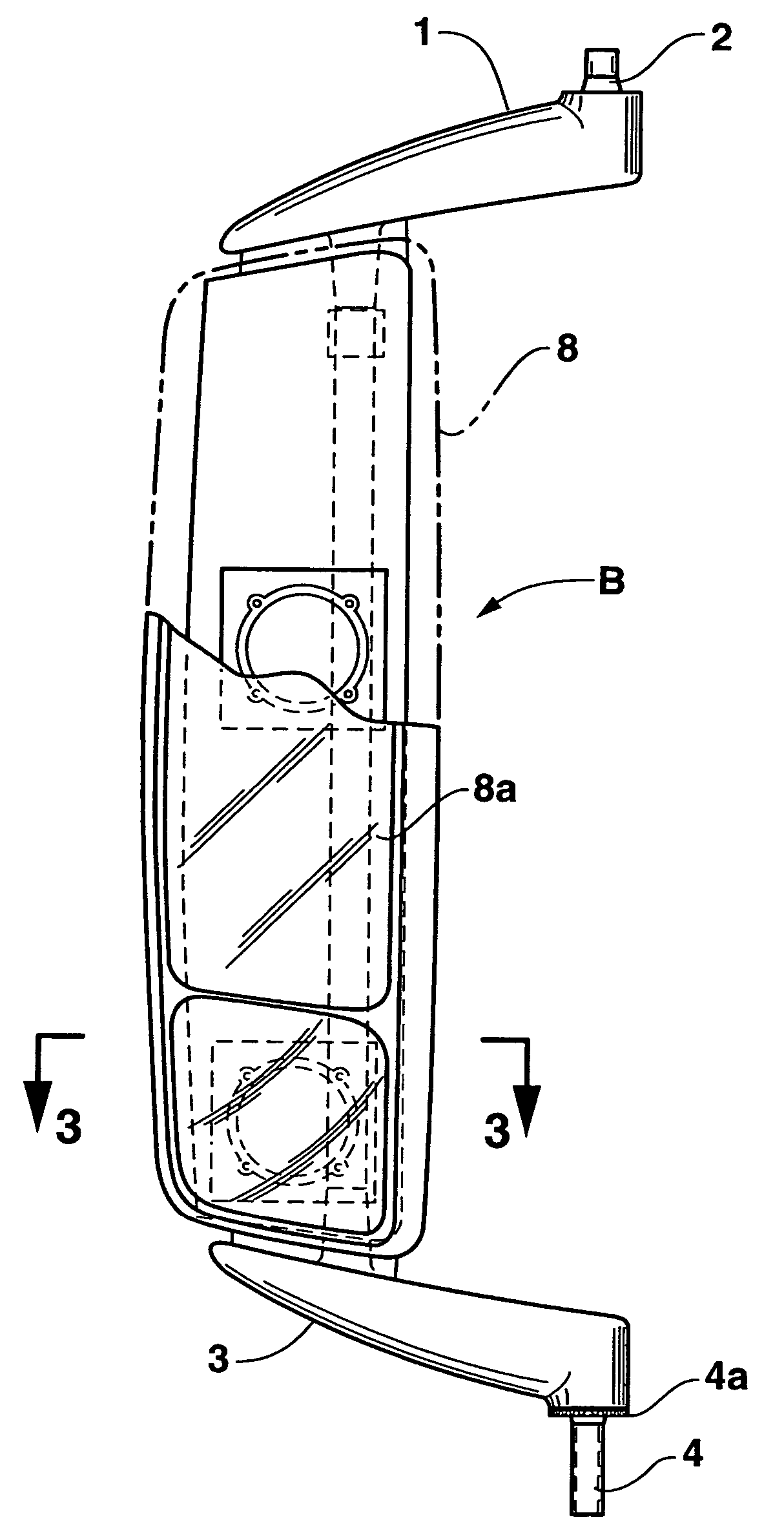
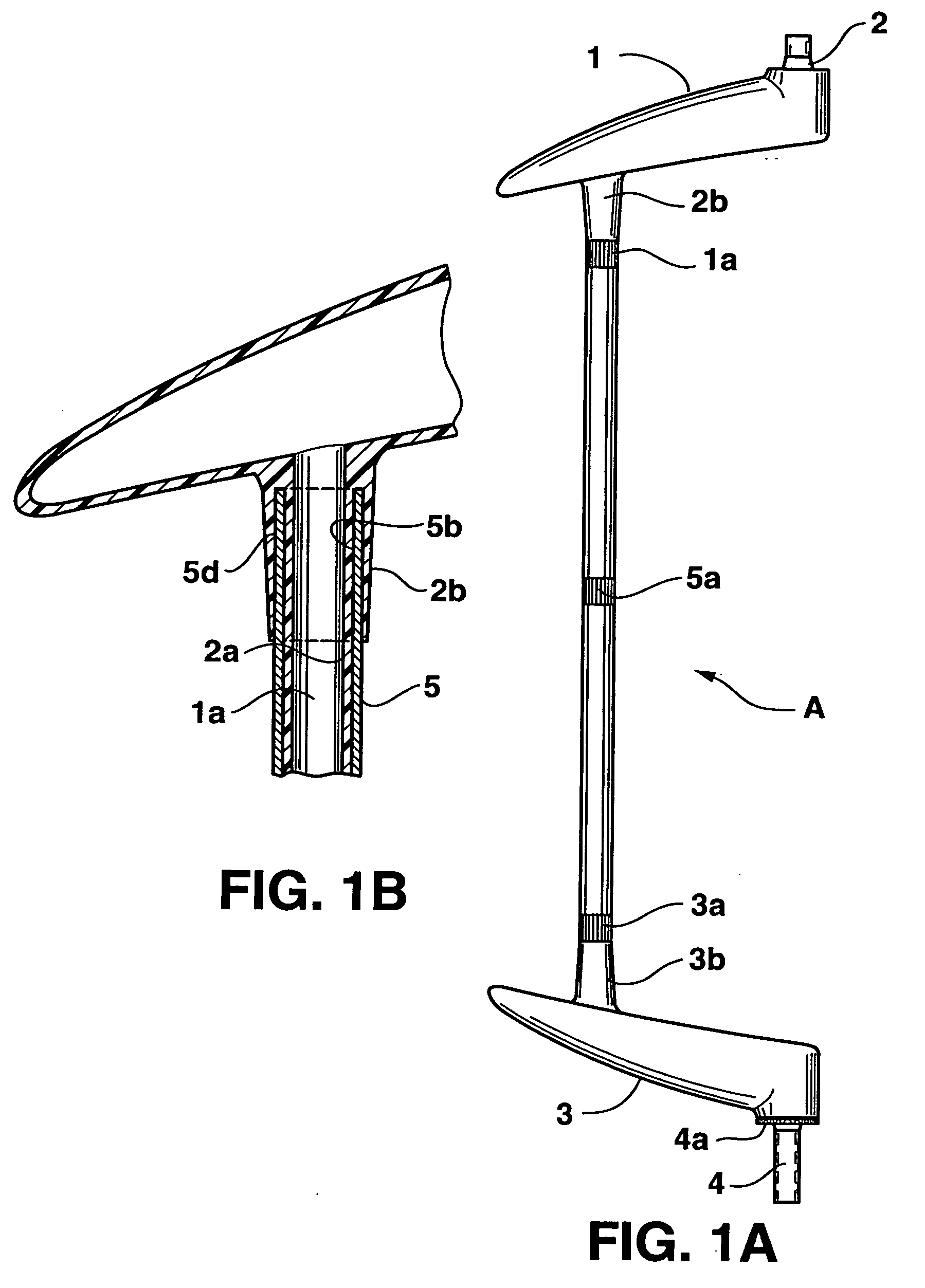
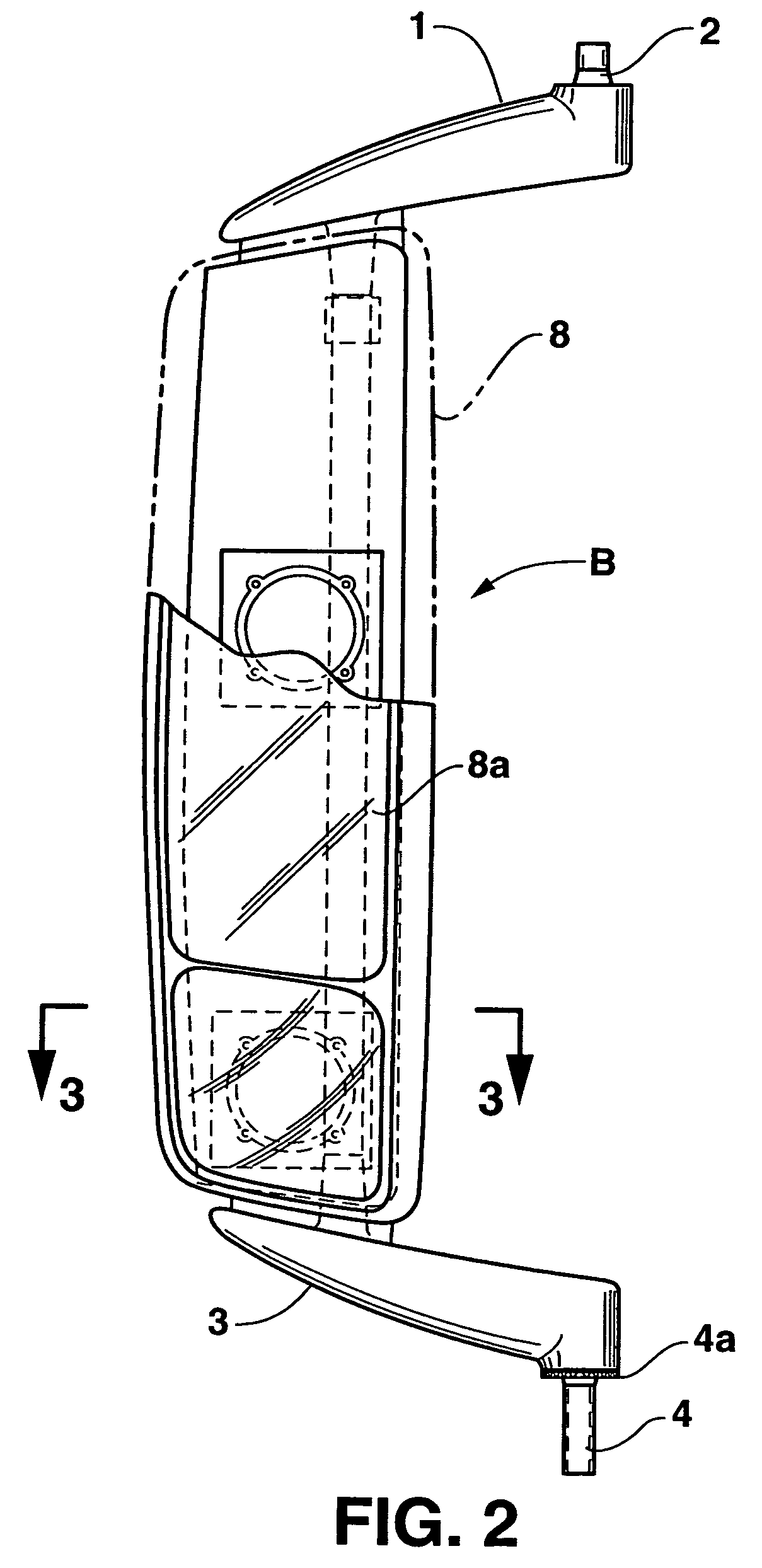
[0030] In the embodiment of FIG. 1A, a mirror support arm assembly, designated generally as A, is illustrated which includes a plastic upper holding arm (1) aerodynamically designed having a conically shaped attachment element (2) mounted on an end for attaching to the vehicle. In a similar manner, support arm assembly A includes a plastic lower holding arm (3) having an attachment element (4) on its end for attaching to the vehicle: Attachment element 4 is preferably in the form of a horizontal toothed raster (4a) with a cylindrical guiding. The attachment element may be fastened to a vehicle by means of a conventional pre-stressed spring and axial clamping ring (not shown), and locked into certain angle position relative to the vehicle by the teeth of raster 4a.

[0031] The assembly includes a base provided in the form of a tube (5). As can best be seen in FIG. 1B, tube 5 is preferably a metal...


PUM


Abstract

A support arm for a vehicle mirror having at least one mirror head with a mirror pane which includes an upper holding arm (1) made of plastic with an anchoring element (2) for mounting on a vehicle, and a lower holding arm (3) made of plastic with an anchoring element (4) at the bottom for mounting on a vehicle. A one-piece base (6) includes a metal tube (5) whose top or, as the case may be, bottom end is securely connected with the upper and lower holding arm, respectively. The base can also be built in the form of a base plate. In this case, the base has a removable positioning wedge (7) that can be removed from the base to change the angle of at least one mirror pane and/or mirror head carried by the base. The positioning wedge is attached to provide an exterior driver-side rear view mirror, and is removed to provide a passenger-side rear view mirror.

Description

BACKGROUND OF THE INVENTION [0001] This invention relates to a rear view mirror assembly for a vehicle, and more particularly to a support arm for a vehicle mirror assembly, especially commercial vehicles. [0002] Heretofore, vehicle mirrors have been provided which encompass at least one mirror head having at least one mirror pane. This mirror pane can be installed in a mirror housing to be either fixed or adjustable or it can be secured directly in a frame. Furthermore, if need be, an adjusting mechanism to adjust the mirror pane relative to the housing, as opposed to the entire housing, can be included. In a simplified variant, the mirror housing is fastened to an essentially U-shaped metal tube bracket whose two ends are then fastened to bearing blocks mounted to the vehicle. For example, in EP 0 090 909 A3, the adjusting mechanism is fixed to the tube bracket by clamping. In the EP 0 590 510 B1, the housing itself is attached to the tube bracket by clamping. The tubing can then ...

Claims


Application Information

Patent Timeline
Patent Type & Authority Applications(United States)
IPC IPC(8): B60R1/06
CPCB60R1/0605B60R1/06
Inventor LANG, HEINRICHPFANZ, JURGENMEIER, MARKUSMAYER, RUDOLF
Owner LANG MEKRA NORTH AMERICA LLC
Why Eureka
Try Eureka