
Remote control system

a remote control and control system technology, applied in transmission systems, non-electrical signal transmission systems, instruments, etc., can solve the problems of inability to adapt to a new electric appliance, inability to input control data for every electrical appliance, and inability to meet the needs of the new electric appliance,

Inactive Publication Date: 2005-06-09
ALPS ALPINE CO LTD
View PDF4 Cites 25 Cited by
  • Summary
  • Abstract
  • Description
  • Claims
  • Application Information

AI Technical Summary

Benefits of technology

[0014] Accordingly, it is an object of the present invention to provide a remote control system using a multifunctional remote control device that saves a user from having to manually input control data on each electrical appliance, and that is capable of adapting to the operation with respect to a new electrical appliance.
[0015] It is another object of the present invention to provide a remote control device that, even if no explanation data on the operating method therefor is stored in the remote control device in advance, is capable of improving its operability by allowing an explanation for operation to be identifiable on the display screen of the remote control device, as well as to provide a remote control system having the same.

Problems solved by technology

However, the former type, i.e., the remote control device having control data stored therein in advance, can remote-control only specified electrical appliances in which control data is stored in advance, and, disadvantageously, cannot adapt to a new electric appliance.
On the other hand, the latter type, i.e., the remote control device into which control data is manually inputted, can indeed adapt to a new electric appliance by inputting control data, but undesirably requires much expense in time and effort to input control data for every electrical appliance.
Regarding such remote control devices, which are included with televisions, audios, air conditioners, and the like, as described above, the methods for operating them have been complicated as these electrical appliances have grown more sophisticated.
In recent times, since each home has been provided with lots of remote control devices corresponding to respective electrical appliances, each home has been suffered from confusion.
However, regarding the multifunctional remote control device, in the case where the explanation data on an operating method therefor is stored in advance, the explanation for operation that can be displayed on the display screen of the remote control device has been restricted to the explanation for the operation with respect to a remote control device, corresponding to a specified electrical appliance having the explanation data stored therein in advance, and it has been impossible to display the explanation for the operation with respect to the remote control device of a new electrical appliance.
Also, because of an increased complexity of the operating method for the remote control device, the remote control device of which the explanation data is stored in advance has had to store a large amount of explanation data on the operating method.
In particular, the multifunctional remote control device has undesirably required a memory for storing a large amount of explanation data on the remote control device concerning each corresponding electrical appliance.

Method used


Image

  • Remote control system
  • Remote control system
  • Remote control system

Examples


first embodiment

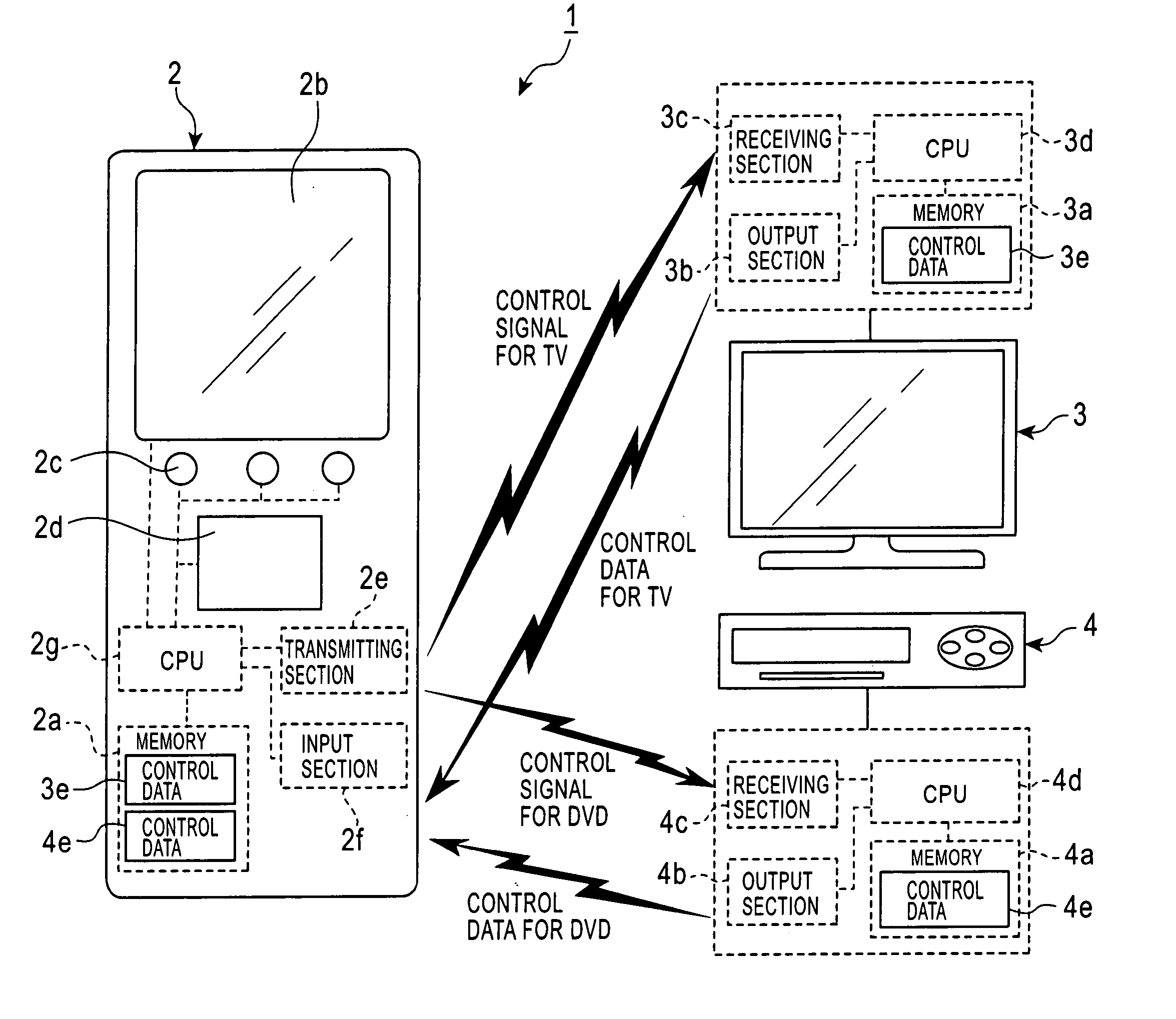
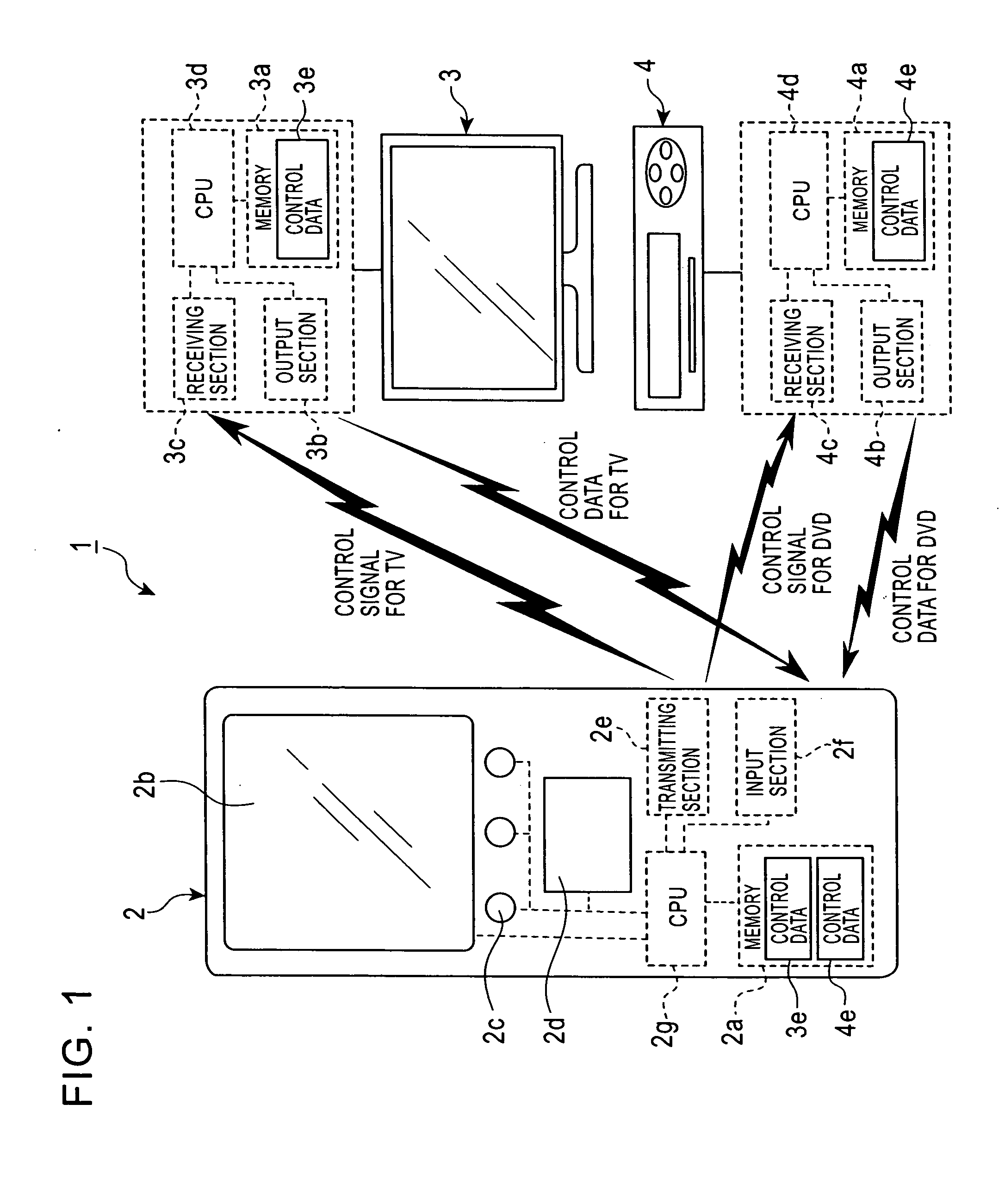
[0039]FIG. 1 is a schematic diagram of a remote control system according to a first embodiment of the present invention. As shown in FIG. 1, this remote control system 1 includes a multifunctional remote control device 2 capable of remote-controlling a plurality of electrical appliances, and electrical appliances that are each remote-controlled by a control signal from the remote control device 2. In the first embodiment, a television 3 and a DVD (digital versatile disc) 4 are taken as examples of the electrical appliances.

[0040] The television 3 and the DVD 4, respectively, perform operations such as the selection of a channel or the adjustment of a volume level; and a replay or recording, by receiving their respective control signals different for each of the operations.

[0041] Memories 3a and 4a each comprising a RAM or the like, of the television 3 and the DVD 4, have control data 3e and 4e stored therein, respectively, in order to output the control data of each control signal...

second embodiment

[0062] Next, a second embodiment according to the present invention will be described with reference to FIG. 4. In the second embodiment, the same or equivalent components as those in the first embodiment are designated by the same reference numerals.

[0063] As shown in FIG. 4, a remote control system 1 according to the second embodiment includes a multifunctional remote control device 2 capable of remote-controlling a plurality of electrical appliances, an electrical appliance (in this embodiment, the television 3) that is remote-controlled by a control signal from the remote control device 2, and a control data storage device 8 in which control data for controlling the television 3 has been stored.

[0064] The control data storage device 8 has an output section 8b for outputting control data 6 to the remote control device 2. The output section 8b is connected with the input section 2f of the remote control device 2 by an USB cable 9. In the memory 8a of the control data storage dev...


PUM


Abstract

A remote control system is disclosed in which a television and a DVD each include a memory in which control data has been stored, an output section for outputting control data to a remote control device, and a receiving section for receiving a control signal from the remote control device. The remote control device includes an input section for inputting control data, a memory for storing the control data, operation buttons and a pointing device for selecting a desired operation of the television and the DVD, and a transmitting section for transmitting the control signal corresponding to the selected operation, to the television and the DVD.

Description

BACKGROUND OF THE INVENTION [0001] 1. Field of the Invention [0002] The present invention relates to a remote control system, and more specifically, to a remote control system using a multifunctional remote control device capable of remote-controlling a plurality of electrical appliances. [0003] 2. Description of the Related Art [0004] Conventionally, for many kinds of electric appliances such as a television, an audio and the like, respective remote control devices capable of remote-controlling them are included, and hence, each home has a plurality of remote control devices corresponding to respective electrical appliances. [0005] With this being the situation, in recent years, a multifunctional remote control device capable of remote-controlling a plurality of electrical appliances by itself, has been put into use. [0006] This type of remote control device includes a type in which control data for controlling each operation of each electrical appliance is stored in advance, and a...

Claims


Application Information

Patent Timeline
Patent Type & Authority Applications(United States)
IPC IPC(8): G08C17/02G08C19/28G08C23/04H02H3/00
CPCG08C17/02G08C19/28G08C2201/92G08C2201/20G08C23/04
Inventor YAMAMOTO, YOSHIHIKO
Owner ALPS ALPINE CO LTD
Learn More