Fuel cell system and its control method

a fuel cell and system technology, applied in the field of fuel cell systems, can solve problems such as fuel consumption increase, and achieve the effect of rapid generation of hydrogen-rich reformate gas

Inactive Publication Date: 2005-06-09
NISSAN MOTOR CO LTD
View PDF6 Cites 28 Cited by
  • Summary
  • Abstract
  • Description
  • Claims
  • Application Information

AI Technical Summary

Benefits of technology

[0006] It is therefore an object of this invention to use excess hydrogen to keep a reformer warm, and to rap

Problems solved by technology

However, the flow of raw material must be

Method used


Image

  • Fuel cell system and its control method
  • Fuel cell system and its control method
  • Fuel cell system and its control method

Examples


Embodiment Construction

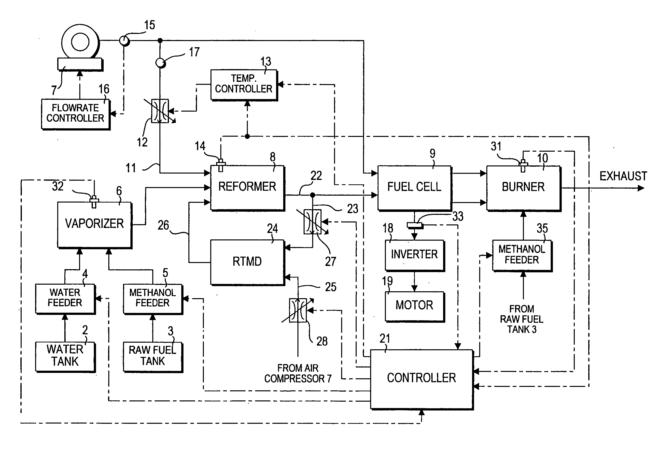
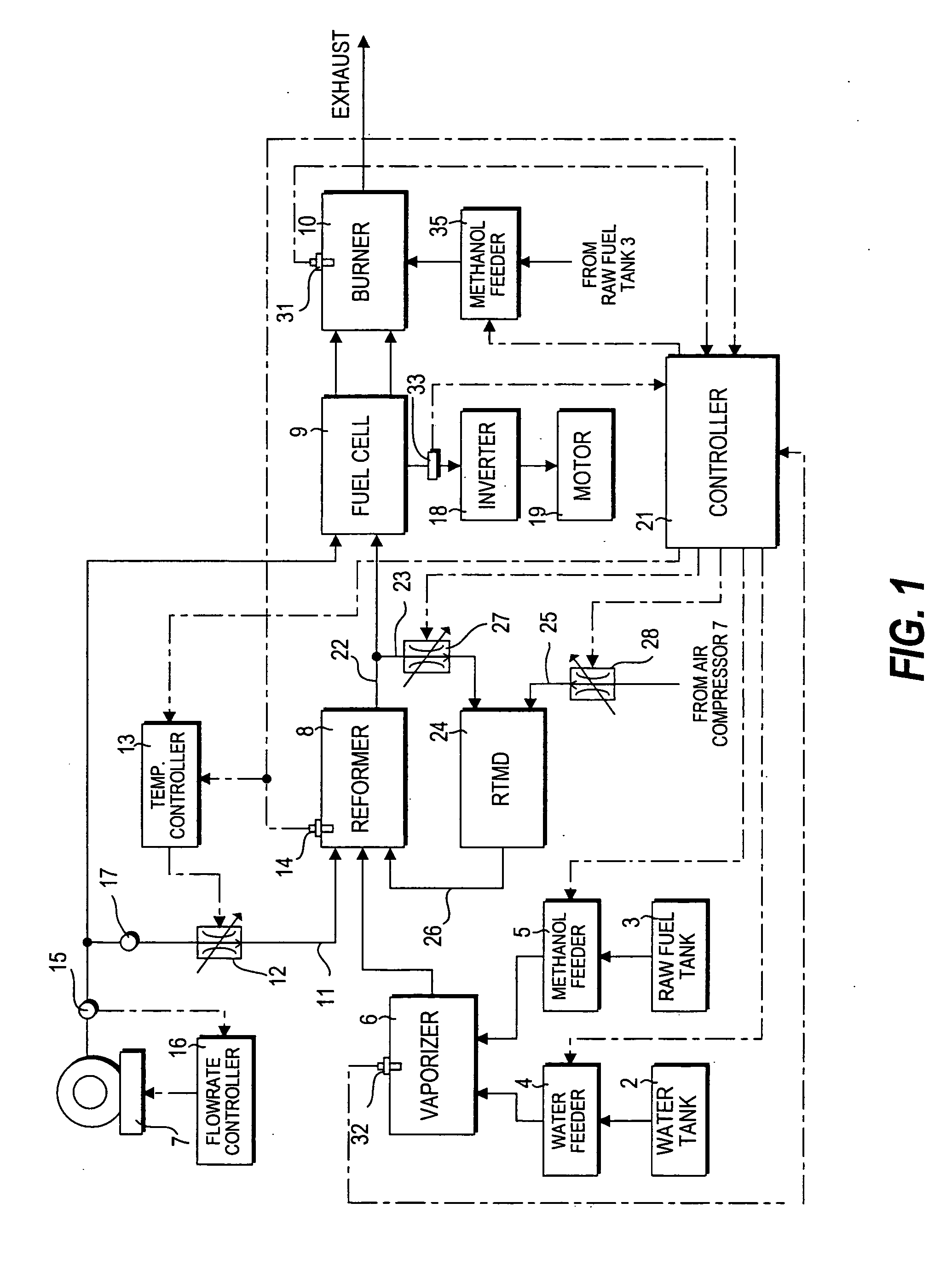
[0023]FIG. 1 of the drawings shows a fuel cell system according to a first embodiment of this invention. First, the basic construction and operation will be described.

[0024] Water in a water tank 2 and methanol in a raw fuel tank 3 are sent to a vaporizer 6 by a water feeder 4 and methanol feeder 5, and heated to become a mixture of water and methanol vapor (raw material vapor) which is supplied to a reformer 8. Here, the water feeder 4 and methanol feeder 5 mainly comprise a feed pump and an injector.

[0025] Target values of the water flowrate and methanol flowrate are computed by a controller 21 based on the required power generation amount of a fuel cell 9, and the controller 21 controls flowrate control devices (injectors) in the feeders 4, 5 so that these target values are realized. If the fuel cell system is installed in a vehicle, the required power generation amount is computed based on the driver's accelerator pedal depression amount.

[0026] Air (oxygen-containing gas) is ...


PUM


Abstract

A fuel cell system comprises a reformer (8) which produces reformate gas containing hydrogen using gas containing oxygen and raw material vapor, and a fuel cell (9) which generates power by reacting hydrogen in the reformate gas with oxygen. A controller (21) determines whether or not excess hydrogen has been produced by the reformer (8), and when it is determined that excess hydrogen was produced, burns the excess hydrogen to keep the reformer (8) warm.

Description

FIELD OF THE INVENTION [0001] This invention relates to a fuel cell system, and more particularly to control when load is decreased. BACKGROUND OF THE INVENTION [0002] JP8-45521A published by the Japanese Patent Office in 1996 and JP11-307110A published by the Japanese Patent Office in 1999 disclose a fuel cell system wherein raw fuel having hydrocarbons as its main component is vaporized, and the raw material vapor and air are supplied to a reformer. In the reformer, hydrocarbons in the raw material and oxygen in the air react together to produce hydrogen-rich reformate gas. The hydrogen-rich reformate gas and air are supplied to the fuel cell, and in the fuel cell, the hydrogen in the reformate gas and oxygen in the air undergo an electrochemical reaction to produce power. SUMMARY OF THE INVENTION [0003] When the aforesaid fuel cell is connected to a load device which consumes power produced in the fuel cell, the raw material and air flowrate supplied to the reformer must be contr...

Claims


Application Information

Patent Timeline
IPC IPC(8): H01M8/04H01M8/06
CPCH01M8/04014H01M8/04022H01M8/04089H01M8/04223Y02T90/32H01M8/0662H01M2250/20Y02E60/50H01M8/0612Y02T90/40H01M8/06H01M8/0267H01M8/04302H01M8/04303
Inventor OKAMOTO, MASARU
Owner NISSAN MOTOR CO LTD
Why Eureka
Try Eureka