Simulated hunting apparatus and method for using same

Inactive Publication Date: 2005-06-09
KENNEN JOHN SCOTT +1
View PDF36 Cites 76 Cited by
  • Summary
  • Abstract
  • Description
  • Claims
  • Application Information

AI Technical Summary

Benefits of technology

[0032] In one, pneumatically-actuated and/or hydraulically-actuated embodiment, the momentum suppression rod includes a cavity and a piston moveable within the cavity. The piston is capable of providing back-pressure to the bow string upon release of the drawn string commensurate to that which an arrow imparts when actually fired from the bow. In this embodiment, the momentum suppression rod has first and second ends, with the first end connected to the archery bow and the second end connected to the bow string. The second end of the momentum suppression rod may extend toward the bow string in a direction generally normal to the bow string and generally along a centerline of travel of the bow string. The cavity may include a cavity wall and inner and outer chambers separated by a displacement valve. The inner chamber may house the piston, and the outer chamber may include first and second compartments, the first compartment containing a compressed gas, such as nitrogen, and the second compartment containing a liquid, such as a low viscosity oil. The displacement valve may be configured to be adjustable from the outside of the momentum suppression rod to allow varying rates of rod release and back-pressure. The piston, the inner and the outer chambers, and the cavity wall are preferably machined to extremely tight tolerances, such as about 0.010+/−0.005 inches, to minimize or prevent rod flex or distortion. One or more proximity sensors are located in the piston cavity; preferably, these sensors have a reaction time in the range of about 0.2-0.9 milliseconds. Release of the drawn bow string causes the piston to reenter the inner chamber and forces the liquid back through the displacement valve and into the outer chamber. Similarly, release of the drawn bow string also causes the piston to reenter the inner chamber and recompresses the gas, thereby supplying sufficient back-pressure on the bow string to sufficiently reduce shock and vibration on the bow necessary to avoid damage to the bow or injury to the user.
[0033] In a preferred

Problems solved by technology

Previous methods of simulated projectile targeting do not include coupling the trajectory software with image editing software to provide a device capable of superimposing the entire flight of a projectile, not just point of impact, on the video recorded by a digital camera.
No known method of integrating these two disparate software applications has been disclosed in combination with

Method used


Image

  • Simulated hunting apparatus and method for using same
  • Simulated hunting apparatus and method for using same
  • Simulated hunting apparatus and method for using same

Examples


Embodiment Construction

[0066] Set forth below is a description of what are believed to be the preferred embodiments and / or best examples of the invention claimed. Future and present alternatives and modifications to this preferred embodiment are contemplated. Any alternatives or modifications which make insubstantial changes in function, in purpose, in structure, or in result are intended to be covered by the claims of this patent.

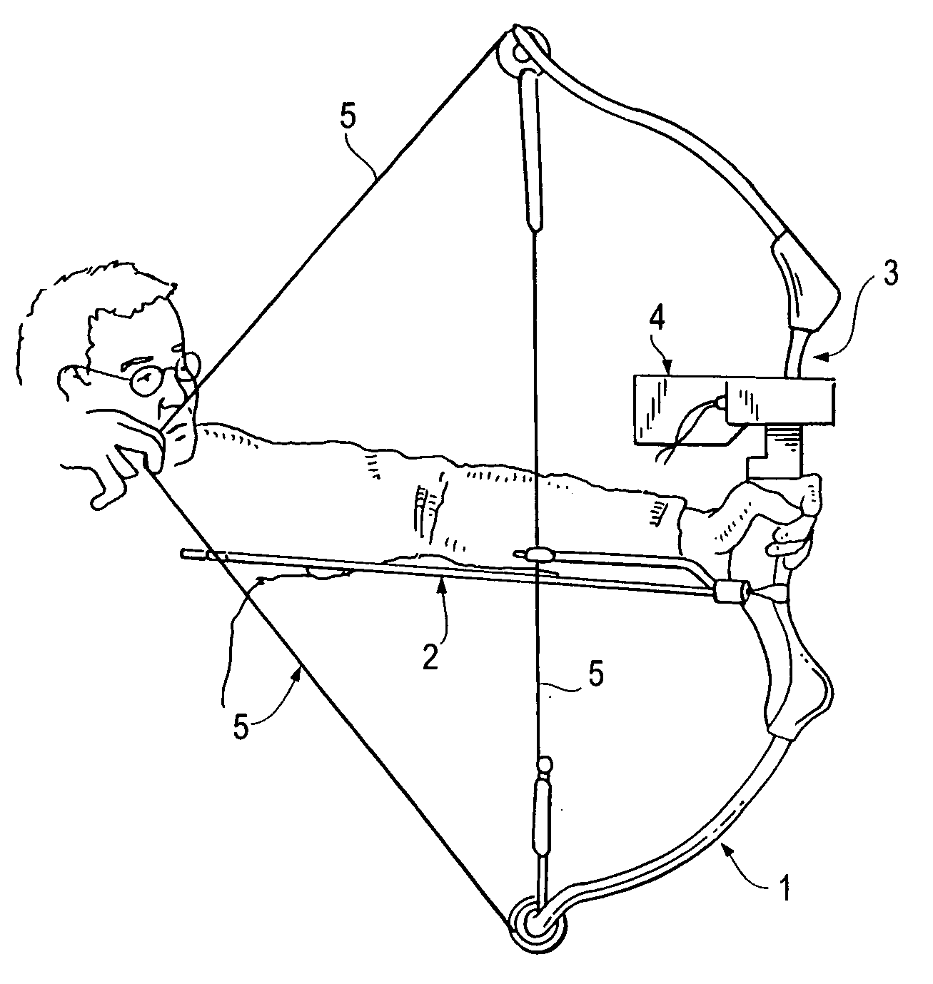
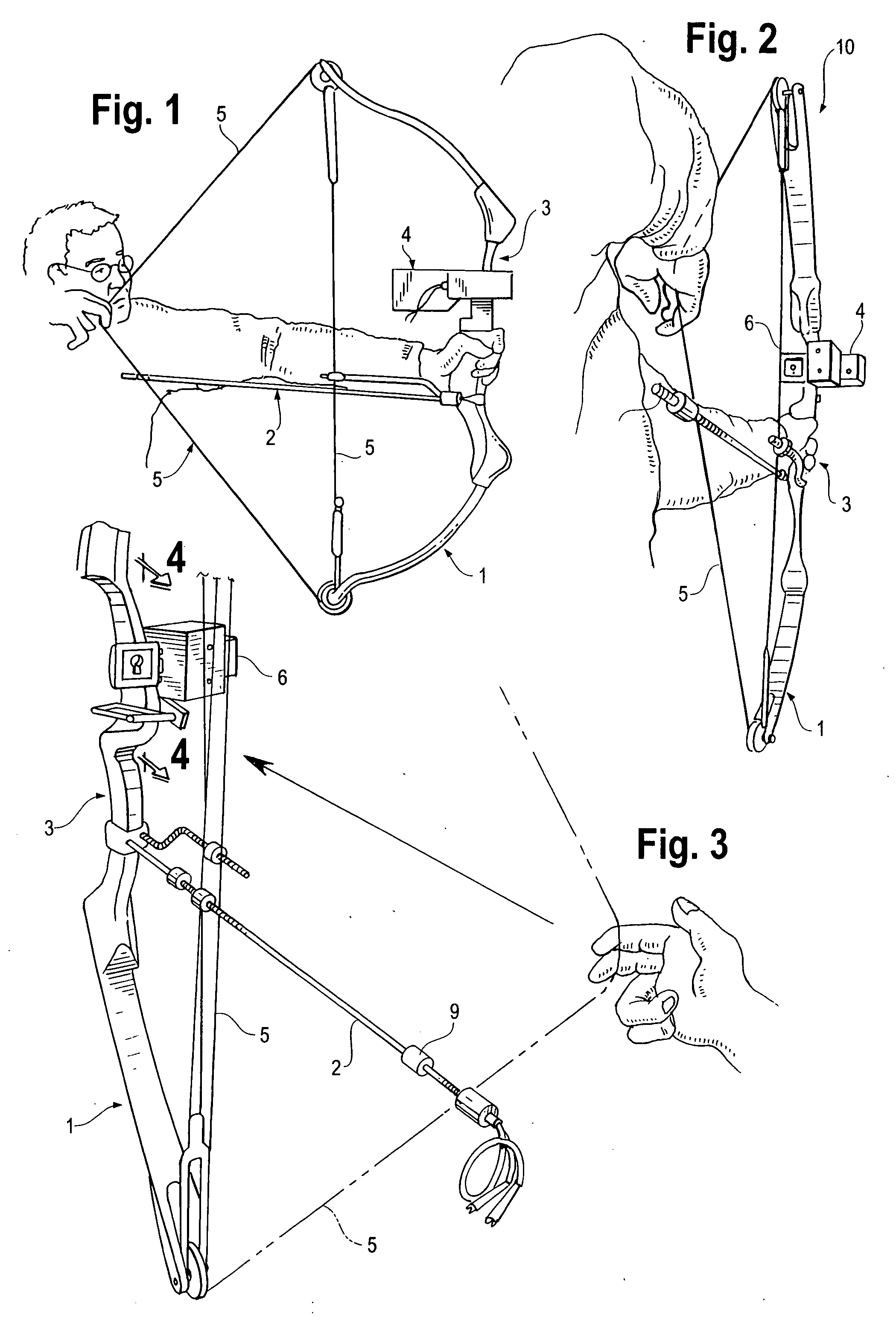
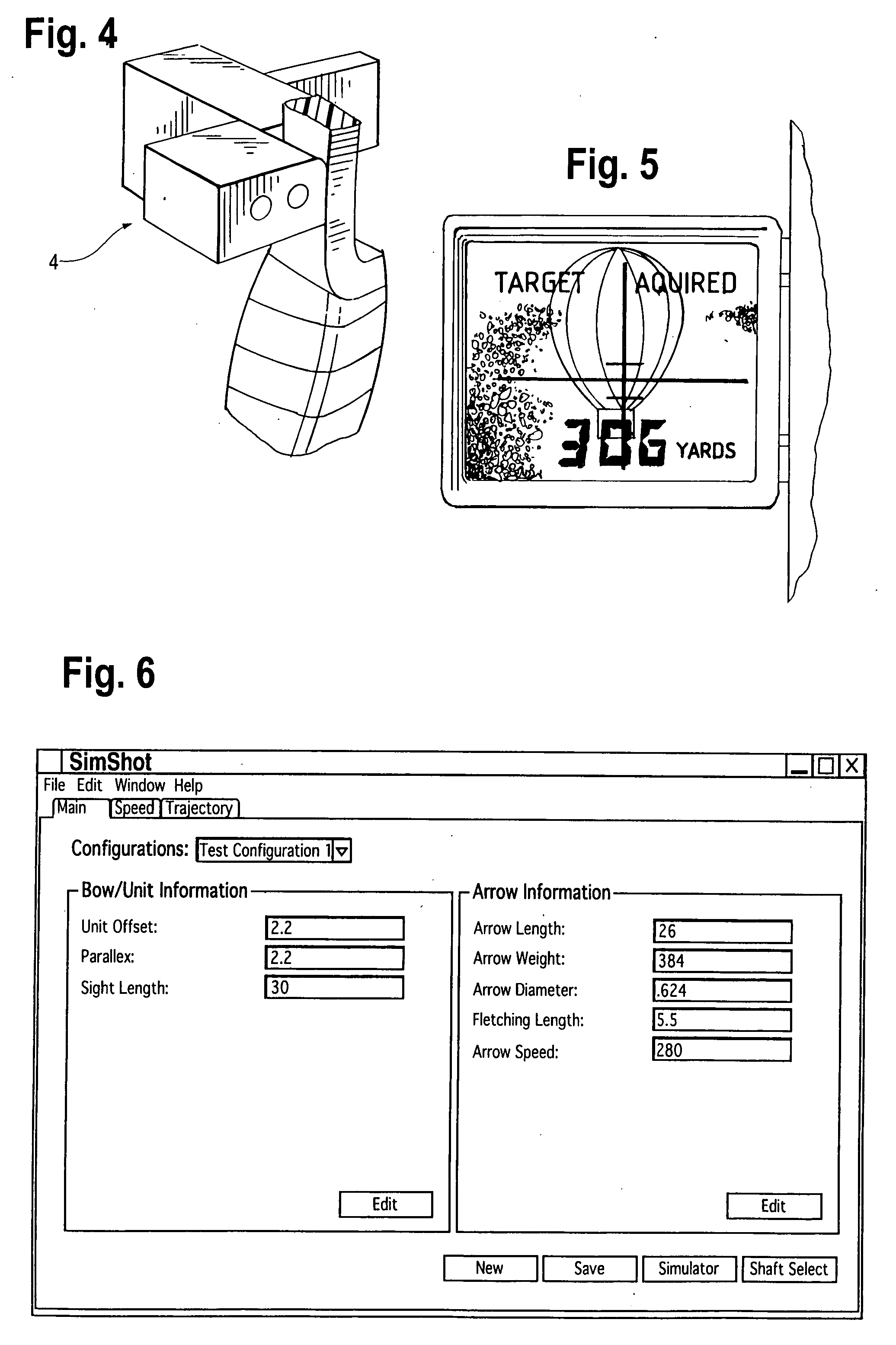
[0067] In accordance with a preferred embodiment of this invention, a unit for use in simulated hunting is generally designated with the reference numeral 10, as shown in FIGS. 1-3. A data capturing hardware unit 4, also shown in FIG. 4, attach to bow 1, preferably by sharing existing mounting holes and / or brackets. Thus, hardware 4 preferably mounts to bow riser 3 using existing mounting holes provided by the bow manufacturer and preferably does not require modifications to the bow. Data capturing hardware 4 is mounted, as shown in FIGS. 1-3, on the side of the arrow rest oppo...


PUM


Abstract

A simulated hunting application for simulating the firing of a projectile such as an arrow or bullet, and displaying its flight path and that of its impact point on an intended target. In a preferred embodiment, the simulated hunting application includes a hunting instrument, such as an archery bow or gun, capable of launching a projectile such as an arrow or bullet; a data capture unit such as a video camera for capturing video data; a range finder for determining distance to target; a display screen for displaying images; trajectory calculating and video editing software programs; and a recording unit for storing the data captured by the data capture unit and data entered into the trajectory calculating software by the user. The flight path of the projectile, as well as its impact point with respect to the intended target, and interplay with background images, may be viewed by the hunter. Safe dry-firing of the hunting instrument may be provided using a momentum suppression rod which also forms part of the present invention. Interplay between the trajectory calculating software and an appropriate clinometer takes into account uphill or downhill shooting.

Description

BACKGROUND OF THE INVENTION [0001] This invention relates to the field of simulated hunting. More specifically, the invention is directed to a simulated hunting device which may be used, for example, to dry-fire a gun or bow equipped with a digital recording device, rangefinding equipment, trajectory calculating software, and image editing software capable of displaying the flight of a bullet or arrow and its impact point on a display screen, allowing hunting without the actual firing of a gun or bow and without harming the target animal. [0002] Various factors have fueled an increasing need for simulated hunting. These factors include increasing population; industrial growth and corresponding shrinkage of huntable land; the presence of large tracts of government-owned, no-hunting lands such as the National Parks; the desire for competitive hunting venues including hunting leagues and / or competitions; and activist groups lobbying against the killing of animals. Accordingly, hunters ...

Claims


Application Information

Patent Timeline
IPC IPC(8): F41A33/00F41G3/26G09B19/00
CPCF41G3/2611G09B19/0038F41B5/1476F41B5/1403F41G1/467
Inventor KENNEN, JOHN SCOTTHEALD, JASON D.
Owner KENNEN JOHN SCOTT
Why Eureka
Try Eureka