
Method for operating a gas turbine and gas turbine system for carrying out the method

a gas turbine and gas turbine system technology, applied in the field of gas turbines, can solve the problems of low nox emissions, co and nox emission behavior, and the residue of relatively cool exhaust gas in relatively short combustion chambers

Inactive Publication Date: 2005-06-16
ANSALDO ENERGIA IP UK LTD
View PDF16 Cites 28 Cited by
  • Summary
  • Abstract
  • Description
  • Claims
  • Application Information

AI Technical Summary

Benefits of technology

[0008] One aspect of the present invention therefore is providing a method for operating a gas turbine that results in a material improvement of the emission behavior during partial load operation without any structural changes to the gas turbine itself, as well as to provide a gas turbine system for carrying out the method.
[0009] A principle of the invention is that the gas turbine that uses a first fuel at full load uses a second fuel at partial load to improve the emission behavior, with the second fuel having a richer mix of higher-value hydrocarbons (C2+) with 2 or more carbon atoms per molecule like ethane (C2H6) and propane (C3H8) compared to the first fuel (the higher-value carbons are hereinafter referred to as C2+).

Problems solved by technology

If no special measures are taken, partial load operation results in an unfavorable emission behavior with regard to CO and NOx.
Another problem with partial load operation of a gas turbine concerns the residue of the relatively cool exhaust gas in relatively short combustion chambers.
Cold gases and short dwell times result in low NOx emissions, but unfortunately also in increased CO / UHC emissions.
The disadvantage with this kind of emissions optimization for partial load operation is the fact that the burners in the main combustion chamber must be specially configured in order to allow for the corresponding operation.
This procedure is difficult to realize in retrospect in existing gas turbines without any special burner arrangement, and thus it is difficult to eliminate emissions issues during partial load operation.

Method used


Image

  • Method for operating a gas turbine and gas turbine system for carrying out the method
  • Method for operating a gas turbine and gas turbine system for carrying out the method
  • Method for operating a gas turbine and gas turbine system for carrying out the method

Examples


Embodiment Construction

[0023] One principle of the present invention recognizes the fact that the emission behavior of a gas turbine can be positively influenced by adding C2H6 and higher molecular hydrocarbons (C2+). It is specifically CO emissions that can be kept below the required emission values across a much larger partial load range than is currently possible. Furthermore, this also has a positive influence on the extinguishing limit, which in turn results in lower NOx emissions.

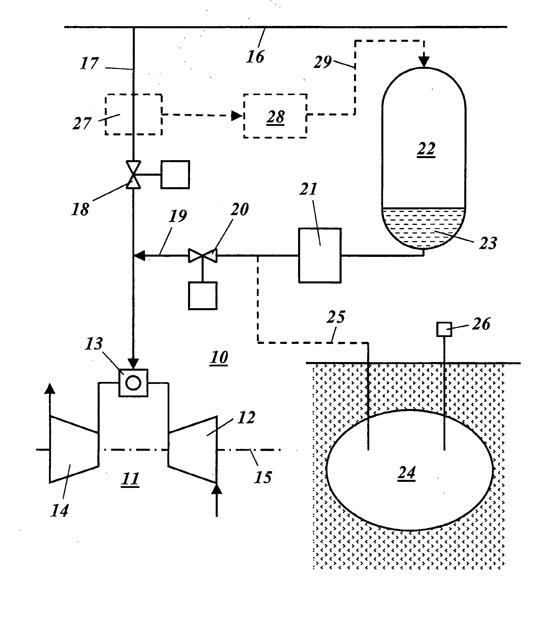
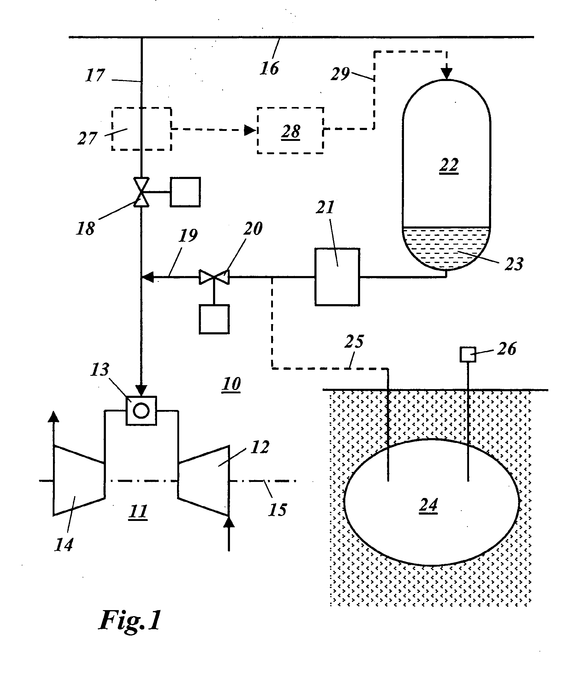
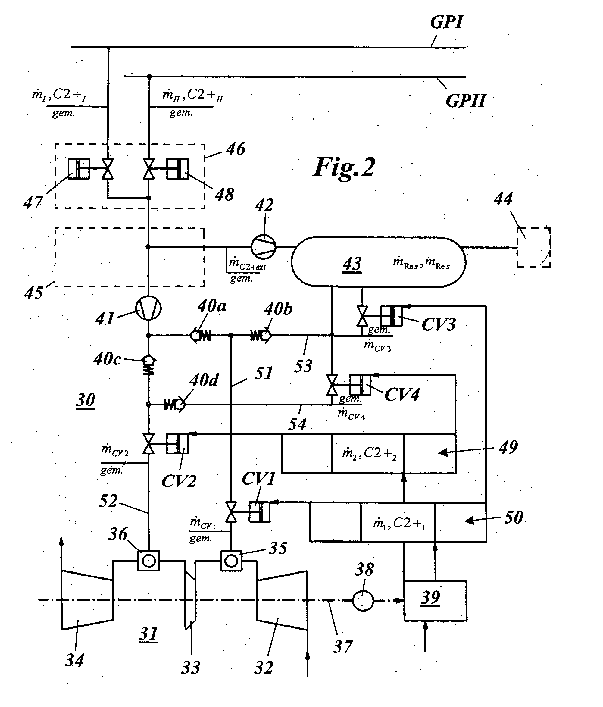
[0024] A suitable gas turbine system is shown in a simplified scheme in FIG. 1. The gas turbine system 10 comprises a gas turbine 11 that is comprised, as is customary, of a compressor 12, a combustion chamber and a turbine 14. Compressor 12 and turbine 14 are arranged on a mutual shaft 15 that is used to drive a generator, not shown in FIG. 1, for power generation purposes. During operation the compressor 12 intakes the air, compresses it and feeds it into the combustion chamber 13, where it is mixed with a, for example, ...


PUM


Abstract

A method for operating a gas turbine uses a first fuel at full load. An improved emission behavior is achieved by operating the gas turbine (11) at partial load with a second fuel, which has a richer mix of higher-value hydrocarbons (C2+) with 2 and more carbon atoms per molecule like ethane (C2H6) and propane (C3H8).

Description

[0001] This application claims priority under 35 U.S.C. § 119 to German application number 103 45 566.3, filed 29 Sep. 2003, the entirety of which is incorporated by reference herein. BACKGROUND OF THE INVENTION [0002] 1. Field of the Invention [0003] The present invention relates to the technical field of gas turbines. It concerns a method for operating a gas turbine, as well as a gas turbine system for carrying out the method. [0004] 2. Brief Description of the Related Art [0005] Usually burners such as the so-called EV burner (double cone burner, ref., for example, U.S. Pat. No. 5,081,844) and the so-called SEV burner (secondary EV burner, ref., for example, an article by F. Joos et al. Development of the sequential combustion system for the GT24 / GT26 gas turbine family, ABB Review 4, p. 4-16 (1998) or U.S. Pat. No. 5,454,220) used in gas turbines are designed for full load operation. Nonetheless it might be necessary to operate the gas turbine at partial load. This might be beca...

Claims


Application Information

Patent Timeline
Patent Type & Authority Applications(United States)
IPC IPC(8): F02C3/20F02C9/40F23K5/00F23R3/36
CPCF02C3/22F02C7/22F02C9/40F05B2270/337F23R3/36F23K5/002F23N2037/08F23N2041/20F05D2270/082F23N2237/08F23N2241/20
Inventor REBHAN, DIETERSTALDER, MARCEL
Owner ANSALDO ENERGIA IP UK LTD
Learn More